Introduction
This post will describe different load balancer designs, the pros and cons of the designs and how they affect the forwarding of packets.
Load Sharing Vs Load Balancing
The terms load sharing and load balancing often get intermixed. An algorithm such as Cisco Express Forwarding (CEF) does load sharing of packets meaning that packets get sent on a link based on parameters such as source and destination MAC address or source and destination IP address or in some cases also the layer 4 ports in the IP packet. The CEF algorithm does not take into consideration the utilization of the link or how many flows have been assigned to each link. Load balancing on the other hand tries to utilize the links more evenly by tracking the bandwidth of the flows and assigning flows based on this information to the different links. The goal is to distribute the traffic across the links as evenly as possible. However load balancing is mostly used to distribute traffic to different servers to share the load among them.
Why Load Balancing?
What warrants the use of a load balancer? Think of a web site such as facebook.com. Imagine the number of users accessing the site. Imagine the number of users uploading pictures or movies to Facebook. There are probably millions and millions of people accessing the site at the same time. Now imagine that a single web server should handle this load on its own. It would be impossible for one server to serve these many users at once. For that reason many web servers are needed and some mechanism is needed to direct incoming HTTP requests to different servers so that the load is shared. Load balancing can be done by products such as F5 Big IP or Citrix Netscaler or the now deprecated product Cisco ACE. Very large companies such as Facebook may very well be rolling their own gear though.
SLB Designs
Server Load Balancing (SLB) is available in different designs. The main designs are routed mode, bridged mode, one-armed mode and Direct Server Return (DSR). We will look at the characteristics of these different designs and how they affect the packet forwarding.
SLB Routed Mode
One of the more popular designs is the SLB routed mode. The SLB device acts as a router and routes between different subnets as can be seen in the topology below.
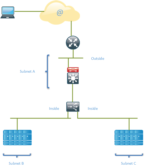
In this design, the SLB device routes between the outside and inside subnets. This design may also be referred to as inline mode due to the SLB device being inline with the servers and networking devices, meaning that all traffic to and from the servers will pass through the SLB device. The services Virtual IP (VIP) addresses are usually in a globally routable public IP subnet, subnet A in the topology. The server farms (physical servers) are then typically in private IP subnets, such as subnet B and subnet C in the topology.
An IP packet from a client will be destined to the VIP address of the service. When the request from a client hits the SLB device, the SLB device uses its algorithm to select a server in the server farm. The destination IP of the packet is then NATed so that the VIP address is replaced with the real IP address of the server. This is destination NAT.
When the packet comes back from the server and hits the SLB device, it will perform source NAT, replacing the source IP of the packet to be the service VIP address instead of the real server IP. This is source NAT.
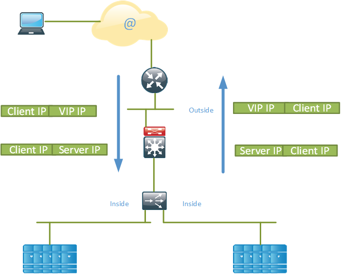
The client IP address is preserved which is good for the organization so that it can keep track of how popular it service is in different regions. The servers would normally use the SLB device as their default gateway on the inside subnet. Note that traffic that comes in on the SLB must also be routed back through the SLB.
In this design, all traffic is sent through the SLB device. This can create some potential issues. The main issue is that the load balancer becomes part of the network infrastructure and must be able to handle all the traffic that flows from and to the servers. Considering the price of load balancers, this is definitely a concern. Traffic that does not need load balancing such as backup traffic will have to pass through the SLB device, which is a waste of resources.
The servers must also be in the right location to be able to connect via Ethernet to the load balancer. The load balancing VLANs may not be available at all locations in the data center.
It’s also worth considering that since the SLB device is inline with all traffic, expect it to be blamed for any believed networking issues, relevant or not.
To overcome the limitations of this designs, an organzation may attempt to do policy based routing or policy based NAT to only send traffic that is to be load balanced across the load balancer and use an alternate path for the rest of the traffic. This increases the complexity and makes it more difficult to troubleshoot the network. Another options is to put an extra Network Interface Card (NIC) in the servers so that the server has one NIC for traffic that is going to the SLB device and one NIC for other traffic such as management traffic and backup traffic. This means that your server has turned into a router though and putting static routes on a server may become a management nightmare.
SLB Bridged Mode
The SLB device can also be run in bridged mode, sometimes referred to “bump in the wire”. This mode is similar to running a firewall such as the Cisco ASA in transparent mode. The device will bridge between two different VLANs.
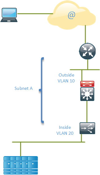
As the topology shows, we have two different VLANs, VLAN 10 and VLAN 20, and they are named “Outside” and “Inside”. These VLANs are part of the same subnet A and the SLB device will perform bridging between the segments. This means that the servers in the servers farm must be located in a globally routable IP subnet. The VIP addresses of services can be in the same or a different subnet but each server farm must be in one IP subnet because the SLB rewrites the MAC address associated with the VIP to be the MAC address of the real server.
The drawback of this design is that bridging is used instead of routing which creates a larger layer two domain and if you deploy it in a redundant configuration, you will have to consider all the Spanning Tree (STP) implications and some links will be blocking.
In this mode the servers would use the router as their default gateway.
SLB One-armed Mode
There is another design that is called the SLB one-armed mode. This design considers load balancing to be just another service and does not force load balancing on all flows.
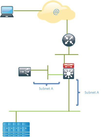
This design may also be referred to as “SLB on a stick”. The SLB device is not directly inline with the traffic so it’s not neccessary for all traffic to pass through it. The SLB VIP and the real servers reside in the same IP subnet.
Inbound end-user traffic is routed to the VIP on the SLB device. The SLB device then performs destination NAT and replaces the destination IP with the IP address of the real server based on the load balancing algorithm. The main difference to the SLB routed mode is that return traffic must be forced through the SLB device. This can be done in several different ways. The first option is to set the SLB device to be the real servers gateway. This forces all non local traffic from the servers to the SLB device which is what we were trying to avoid in the first place. The second option is to use PBR to “push” or “deflect” the appropriate outbound traffic towards the SLB device. The final option is to do source NAT on the SLB device so that the source IP of the packet is changed from the end user IP to be the IP of the SLB device. This is the option that makes most sense in my opinion.
The advantages of the one armed design is that the SLB device and the server farms can be placed more freely in the network and that not all traffic has to pass through the SLB device.
Direct Server Return
There is also a design called Direct Server Return (DSR) which only load balances flows in one direction, from the end user towards the servers but not from the servers towards the end-user. The idea of this design is that normally requests may be quite small but replies will generally be larger. For example, there could be incoming requests at 100 Mbit/s but outgoing replies to those requests generating 800 Mbit/s worth of traffic. This increases the risk that the load balancer becomes a bottle neck. In the DSR mode, the server is allowed to respond directly to the client, putting less load on the load balancer.
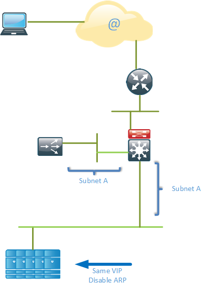
With this design, multiple servers are configured with the same IP address. ARP must be disabled on the servers so that they do not respond to ARP requests for the VIP, otherwise they would attract incoming traffic that is supposed to go to the load balancer. When the traffic hits the load balancer, it will rewrite the destination MAC address to be the MAC address of the real server. The server can then directly respond to the packet and send it towards the end user.
One advantage of DSR is that the end user IP is preserved which increases the visibility. Typical inbound traffic is much smaller than outbound traffic, organizations such as Yahoo! typically have 1:8 ratio for their traffic. With the DSR design, less stress is put on the load balancer.
There are also several drawbacks of DSR.
- The backend servers have to do more work, responding both to health check requests with their own IP address and to content requests with the VIP assigned by the load balancer.
- Cookie insertion and port translation is not possible.
- ARP must be disabled on the servers to not attract traffic that is destined for the load balancer.
- Application acceleration is not possible because the load balancer does not handle outbound traffic
- Protocol vulnerabilities are not protected.
- Caching needs to take place on routers using Web Cache Communication Protocol (WCCP). This increases the complexity of the network.
- There is no way to handle SOAP/Error/Exception issues. The end user will receive classic error messages such as 404 or 500 without the load balancer having the chance to retry the request or even notifying the administrator.
Increasing Availibility
One method to increase the availability of these designs or any design for that matter is to use anycast. Anycast is when the same IP address is configured on multiple servers in (normally) different locations. The most common example of an anycasted service is the root DNS servers. The root DNS servers are spread across the world and requests to the root servers are handled by the “closest” server which is normally what is considered the shortest path according to BGP policies.
Anycast can be used for the load balancing designs mentioned above so that the same VIP is served by multiple data centers. This may increase the routing complexity though so take that into consideration before deploying anycast.
I hope this post has given you a brief overview of load balancing and the different designs that are available.
Hi,
thanks for the detailed description of how each mode works. It’s not clear to me why there are 2 VLANs required in the bridged mode. I’m used to having one VLAN/subnet and since there’s only subnet A involved, I don’t see why this mode has two VLANs.
Thanks for the feedback. I don’t think it’s a requirement. I have seen the same VLAN used as well. One benefit of having two different VLANs would be if you want to implement a private VLAN solution, I suppose.
Thank you so much for those precious informations
For the SLB Routed Mode, I could just static route my traffic out the same interface instead of adding additional NIC (based on destination prefixes and external Vs. private).
Useful post.
Thanks,
Hosam Badreldin
Yes, definitely possible. Only a matter of administrative overhead and keeping the routes there after a reboot as well 🙂 Probably many people forget to make the routes permanent.
It is very informative article Daniel.
thanks.
Great posts! As I go through the blog, I feel like I am on the field deploying a live infrastructure. Keep it up, I am reading and reading.
nice 🙂
In Bridge mode two different VLAN is required when device(LB) is connected inline via Switch, so that traffic will transparently pass via LB and will be load balance accordingly.
I’m confused,
If we have this design :
POOL_SERVERS 10.10.10.99 ——– F5 VIP 10.10.10.100 ——– ROUTER GATEWAY 10.10.10.1——-INTERNET X.X.X.X
You say :
**The VIP addresses of services can be in the same or a different subnet but each server farm must be in one IP subnet because the SLB rewrites the MAC address associated with the VIP to be the MAC address of the real server”**
How could this be possible for the VIP to be on different Subnet ? How ARP could works knowing that the “ROUTER GATEWAY” doesn’t know the VIP SUBNET ?
Do you have any reference book?