Introduction
As a network architect you should not have to know all the details of the physical and data link layer. What you need to know though is how different transports can support the topology that you are looking to build. If you buy a circuit from an ISP, what protocols can you run over it? Is running MPLS over the circuit supported? What’s the maximum MTU? Is it possible to run STP over the link? This may be important when connecting data centers together through a Data Center Interconnect (DCI).
To be able to connect two data centers together, you will need to either connect via fibre or over a wavelength or buy circuits from an ISP. Renting a fibre will likely be more expensive but also more flexible if you have the need to run protocols such as MPLS over the link. For a pure DCI, just running IP may be enough so there could be cost savings if buying a circuit from an ISP instead.
For a big enough player it may also be feasible to build it all yourself. This post will look at the difference between Coarse Wave Division Multiplexing (CWDM) and Dense Wave Division Multiplexing (DWDM) and some of the available optical protection schemes.
CWDM
CWDM supports up to 16 channels (wavelengths) in the spectrum grid from 1270 to 1610 nm with a 20 nm channel spacing. Every channel can operate at 2.5, 4 or 10 Gbit/s. CWDM can’t be amplified because most of the channels are outside the operating window of the Erbium Doped Fibre Amplifier (EDFA) that is used in DWDM systems. This means that CWDM only reaches approximately 100 km. CWDM uses cheaper uncooled lasers compared to DWDM which makes the investment lower compared to DWDM.
DWDM
DWDM supports up to 80 channels (wavelengths) in what is called the Conventional band or C band. These channels exist in the 1550 nm region. A DWDM channel can support rates of 1, 2.5, 4, 10, 40 or 100 Gbit/s. DWDM can be transported much longer distances because it operates in the operating window of EDFA. DWDM can be transported up to 1500 km. The denser channel spacing requires more exact lasers and therefore temperature stabilized lasers as opposed to CWDM. DWDM used to be significantly more expensive than CWDM but products have evolved and moved into mass production to close the gap between CWDM and DWDM.
These are some things to consider when choosing CWDM or DWDM:
- Distance that needs to be covered
- The number of channels needed
- The data rate used per channel
- The number of fibers available
Resiliency
When building networks with wavelengths over DWDM, how can we build resilient networks? First, let’s look at the standard setup which is an unprotected path.
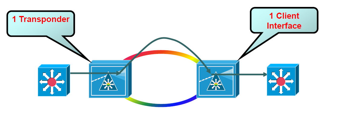
Building an unprotected path means that a fibre cut, transponder failure or client failure will bring the circuit down. We have to be careful when provisioning circuits because sometimes a router has multiple uplinks and one interface is named “redundant xxx” but it’s actually a wavelength transported over the same physical fibre.
One option to build resiliency is to use the client protected mode.
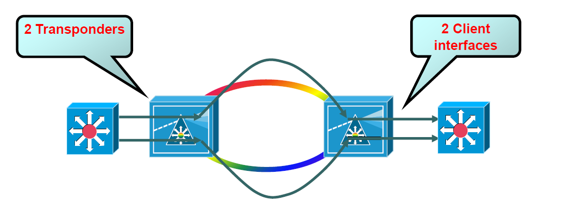
Two client and two trunk lasers (transponders) are needed and two optically unprotected paths are provisioned. This means that there are two separate paths available but the optical layer does not keep track which path is used or not, this is up to higher layer protocols. Normally routing would be run such as OSPF or ISIS and two paths would be available. Metrics could be tweaked to create a primary path and a backup path. It would be up to BFD or routing protocol hello timers to detect the failure of the optical path if link down is not detected. This may be slower than a technology such as SDH which could switch to a protected path within 50 ms. It’s desirable that if one end of the link fails that the other end also gets Loss of Signal (LoS) to not have to relay on hello protocol timers.
Another model is the optical splitter protection mode.
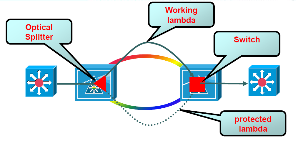
This model uses only one client and one trunk laser (transponder). It protects against fiber breaks but not against failure of the client or transponder. Switching to the other path would be based on LoS and should be fast but I don’t know the exact numbers.
Finally, let’s have a look at the line card / y-cable protection model.
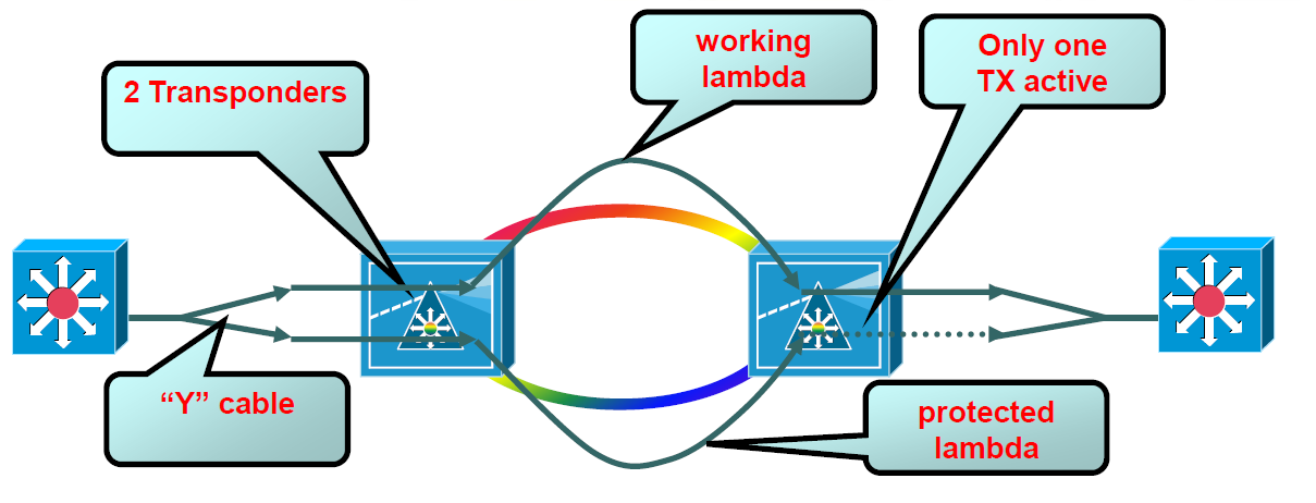
Compared to the client protected mode, only one interface is used on the routers which is then split into two different client ports. Only one TX is active on the other side. Two client ports and two trunk lasers (transponders) are needed for this model. Compared to the client protected mode, we save on the cost of transceivers on the routers but we only have one active path and a failure of the transceiver on the router means both paths will be down. We have to make a decision how likely the transceiver on the router is to fail as opposed to a fiber break. Also here LoS can be used to detect failure and activate the TX that is not currently active. This should be very fast as well.
This post should give you a basic view of CWDM, DWDM and what protection schemes that are available.
Hey, can we use LoS with client protected mode ?