It is well known that VXLAN supports bridging frames, that is, forwarding frames that belong to the same L2 segment. In the beginning, this is all that was supported. There was no VXLAN routing. In essence, the HW didn’t support taking a VXLAN encapsulated packet, decapsulating it, and then performing a L3 lookup. This meant that another device was needed to do the L3 lookup. Think of it as router on a stick where the VTEP would decapsulate the packet and forward it (based on L2 lookup) to a gateway. This gateway needed to have L3 interfaces for all the L2 VNIs that needed routing. Now, this is still applicable in a design where a FW should inspect traffic between all VNIs, but HW has supported for a long time to do VXLAN routing, that is, taking packet from one VNI and routing it to another VNI. This is referred to as Integrated Routing and Bridging (IRB), as the device is capable of both bridging and routing packets. IRB is described in RFC 9135.
There are two types of IRB, asymmetric and symmetric. Asymmetric vs symmetric refers to how the lookup is performed to do routing. Let’s first take a look at asymmetric IRB. Let’s say that there are two L2 VNIs, VNI 10000 and VNI 20000 with Server-1 in VNI 10000 and Server-4 in VNI 20000. Server-1 is connected to Leaf-1 and Server-4 is connected to Leaf-4. Server-1 is sending an ICMP Echo request to Server-4. The following then takes place:
- Server-1 forwards the packet to Leaf-1 with destination MAC of SVI of Leaf-1.
- Leaf-1 does L2 lookup and sees its own MAC. This means the packet should be routed.
- Leaf-1 does L3 lookup based on VRF associated with SVI. Packet needs to be routed to SVI of VLAN 20
- Leaf-1 checks ARP cache to get MAC address of Server-4.
- Leaf-1 checks MAC address table to find what VTEP to forward packet to for Server-4.
- Leaf-1 gets the VNI associated with VLAN.
- Leaf-1 encapsulates the packet and sends it to Leaf-4.
- Leaf-4 decapsulates the packet.
- Leaf-4 does L2 lookup based on VNI and destination MAC of packet.
- Leaf-4 forwards the packet to Server-4.
The packet at the different hops is shown below:
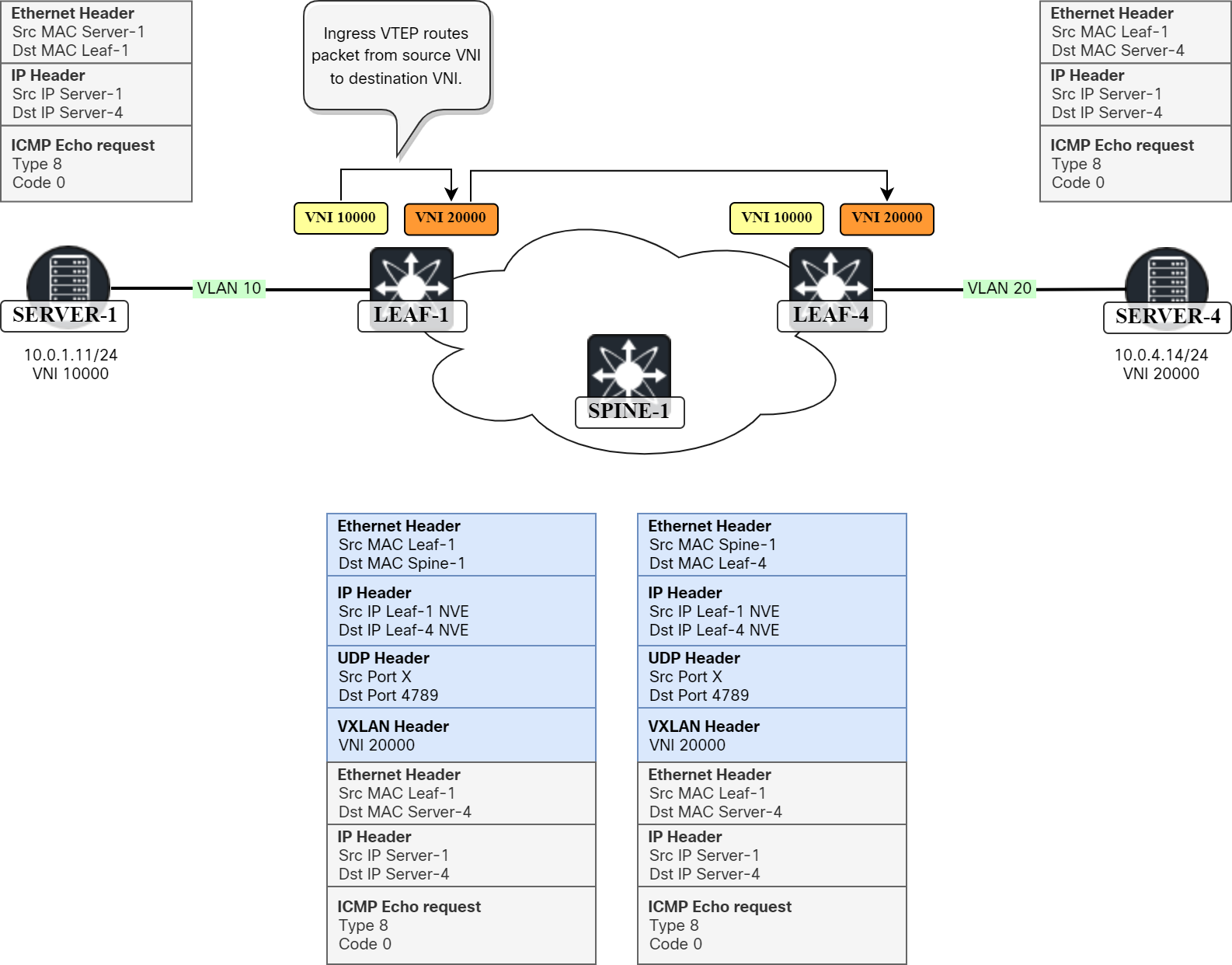
In summary, Leaf-1 routes the packet from VNI 10000 to VNI 20000 and then bridges it within VNI 20000. This means that when the packet hits Leaf-4 it can simply bridge it and no routing is needed. Now, when Server-4 responds to the ICMP Echo request, Leaf-4 will route the packet from VNI 20000 to VNI 10000 and then bridge it within VNI 10000. This is where the name asymmetric comes from as Leaf-1 and Leaf-4 aren’t performing the same operation. Leaf-1 routes from VNI 10000 to VNI 20000 and then bridges (L3 lookup and L2 lookup) while Leaf-4 only does a L2 lookup to forward. In the reverse direction, the opposite takes place. This has the following consequences:
- VNI 10000 and VNI 20000 must be configured on both devices.
- VLAN 10 and 20 (or other equivalent VLANs) must be configured on both devices.
- SVIs for VLAN 10 and 20 (or other equivalent VLANs) must be configured on both devices.
- ARP cache is populated for all VRFs.
- MAC address table is populated for all VLANs.
- Route table is populated for all VRFs.
- Must generate and process BGP updates for all VNIs.
This is obviously not very burdensome with only two VNIs, but in a real network with possibly hundreds of VLANs and VNIs this means that you must keep your configurations in sync and configure all the VLANs, SVIs, and VNIs. There are some designs where a host should be able to be connected to any leaf and then for example vMotion to another leaf seamlessly. In such a design, asymmetric IRB would work nicely, but in general asymmetric IRB is today considered a waste of resources and suboptimal compared to symmetric IRB as it consumes a lot of resources when it comes to populating all the forwarding tables like the ARP cache, MAC address table, and routing table.
The other mode of operation for IRB is symmetric mode. With symmetric mode, both VTEPs perform L3 and L2 lookup. There is a L3 VNI used to perform routing. Let’s walk through the same example with VNI 10000 and VNI 20000, but now there is also a L3 VNI 10001:
- Server-1 forwards the packet to Leaf-1 with destination MAC of SVI of Leaf-1.
- Leaf-1 does L2 lookup and sees its own MAC. This means the packet should be routed.
- Leaf-1 does L3 lookup based on VRF associated with SVI. Packet needs to be routed to L3 VNI.
- Leaf-1 encapsulates packet and sets L3 VNI and DMAC of inner Ethernet header to Router MAC of Leaf-4.
- Leaf-4 decapsulates the packet.
- Leaf-4 does L3 lookup based on VNI and finds local route towards Server-4.
- Leaf-4 checks ARP cache to find MAC of Server-4.
- Leaf-4 checks MAC address table to find outgoing port for Server-4.
- Leaf-4 forwards the packet to Server-4.
The packet at the different hops is shown below:
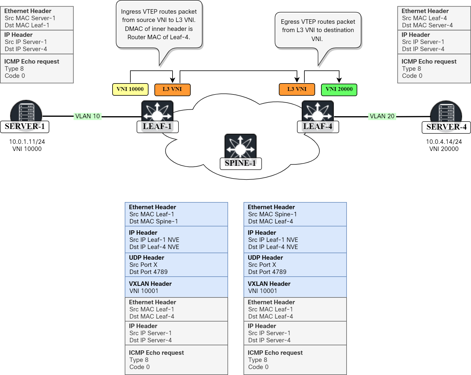
Here VNI 10001, the L3 VNI, is used for forwarding as opposed to the L2 VNI that was used with asymmetric IRB. The inner Ethernet header is using the MAC address of the other leaf as destination. This MAC is learned based on the Router MAC extended BGP community that I covered in a previous post. The name symmetric comes from that both the VTEPs are performing both L2 and L3 lookup. The ingress VTEP first does a L2 lookup and then L3 lookup. The egress VTEP first does a L3 lookup and then L2 lookup.
The advantage of symmetric IRB is of course that we don’t need all the L2 VNIs, VLANs, and SVIs for networks that aren’t used. This also means a lot less forwarding state to maintain such as MAC address tables, ARP cache, and routing table.
In this post we learned:
- How with asymmetric IRB, the ingress VTEP does L3 lookup and L2 lookup and egress VTEP only L2 lookup.
- That with symmetric IRB both the VTEPs do L2 and L3 lookups.
- That asymmetric IRB requires VTEPs to have same configuration in regards to L2 VNIs, SVIs, and VLANs.
- That asymmetric IRB requires more state to be kept than symmetric IRB.
I hope this has been informative and I’ll see you in the next post!
Hi Daniel,
Thanks for just again another great explanation on the subject.
Is the IRB mode of operation the reason that you need to create an extra SVI in the L3 VNI even if you only do routing within that VNI. Cisco gives lots examples on how to configure L3 routing within an BGP EVPN VxLAN solution. But so far I have not found a clear explanation on why this extra SVI is needed. The SVI even does not need an IP address. To me it seems like a kind of hook to make L3 routing work in BGP EVPN VxLAN
Hi Fred,
Yes, the SVI is needed with Symmetric IRB as this is how we build a working data plane. Like you said, there is no IP on the SVI, but the MAC address is needed and it is advertised in RT2 and RT5 as Router MAC BGP extended community. Ingress VTEP first does L2 lookup and sees that destination MAC of frame is to itself. It then does L3 lookup which is pointing to the egress VTEP. To get the egress VTEP to do a L2 lookup, the inner Ethernet destination MAC is set to the Router MAC of egress VTEP.
What exact difference in configuration symmetrical vs assymetrical irb? I can’t find this information.