This post is going to be a real deep dive! First, I want to send my sincere thanks to the maestro Peter Palúch and the guru Ivan Pepelnjak for helping me research this topic. Ivan wrote a couple of great posts on unnumbered links:
- Packet Forwarding and Routing over Unnumbered Interfaces
- Running OSPF over Unnumbered Ethernet Interfaces
In VXLAN fabrics, it is quite common to build the underlay using unnumbered links. The concept is not new. In the past, unnumbered links were mainly used with point to point serial links using encapsulation such as Point-to-Point Protocol (PPP). There was a time before variable length subnet masks where addressing interfaces could be very wasteful. Using unnumbered links reduced the need for addressing. It was generally not allowed on multi access interfaces such as Ethernet, though. Even though we often use Ethernet as point to point links.
What benefits do unnumbered links provide in today’s networks? There are a few:
- Reduce the number of IP addresses needed to address links.
- Less unique configuration for each device.
- Fewer lines of configuration.
Let’s dive deeper into each of these:
Reduced need of IP addresses – While these may be private IP addresses, it still takes time to assign and configure the links. It also means adding the links to an IPAM or similar. For example, in a fabric with 2 spines and 16 leafs, still not a huge fabric by any means, 32 subnets would be needed to address the links.
Less unique configuration – This makes it easier to create templates to automate the deployment of devices. For example, when adding a new leaf to a fabric, only the loopbacks will be unique and the rest of the configuration in regards to OSPF and VXLAN can be exactly the same as the other leafs.
Fewer lines of configuration – This may not sound like much but having fewer lines of config to parse is good. Especially at 2 AM. Every line of config costs something. Whether it be financially or just by having to maintain the configuration.
Before we dive into how IP unnumbered works, let’s recap how packets are routed. When using addressed links, the main benefit of having an IP address is that it makes it easy to find the outgoing interface and hence how to encapsulate the frame (which is the actual goal). Assume that we have two routers running OSPF, R1 and R2 in 192.0.2.0/31 where R1 is .0 and R2 is .1. R2 is advertising 198.51.100.0/24. The logic would be as following:
- R2 advertises 198.51.100.0/24 into OSPF.
- R1 receives the LSA coming from 192.0.2.1.
- R1 runs SPF and the best path to 198.51.100.0/24 is via R2.
- R1 does a lookup to find the outgoing interface towards 192.0.2.1.
- Based on the outgoing interface, R1 knows what source and destination MAC to encapsulate the frame with.
- This is information that has been derived from ARP.
As you can see, the IP address on the interface is a key factor to finding the outgoing interface. This is something that we will have to overcome with unnumbered links.
I’ll be describing unnumbered for NX-OS although most of the concepts should apply to any OS. First, let’s try to configure unnumbered on an Ethernet interface:
Leaf3(config)# int eth1/4
Leaf3(config-if)# ip un?
                     ^
% Invalid command at '^' marker.
The command is not there! What now? This is because we have a broadcast type interface:
Leaf3# show int eth1/4 | inc medium
  Encapsulation ARPA, medium is broadcast
On NX-OS, the interface must first be declared as point to point before the command is allowed:
Leaf1(config)# int eth1/4
Leaf1(config-if)# medium p2p
Leaf1(config-if)# ip unnumbered ?
  loopback  Loopback interface

Leaf1(config-if)# ip unnumbered lo0
Leaf1(config-if)# show int eth1/4 | in medium
  Encapsulation ARPA, medium is p2p
Let’s look at an interface that has already been configured as unnumbered:
Leaf1# show ip int eth1/1

IP Interface Status for VRF "default"(1)
Ethernet1/1, Interface status: protocol-up/link-up/admin-up, iod: 5,
  IP unnumbered interface (loopback0)
  IP broadcast address: 255.255.255.255
  IP multicast groups locally joined:
      224.0.0.2  224.0.0.1  224.0.0.13  224.0.0.5
Notice that it is unnumbered to loopback0. Loopback 0 is configured with IP 192.0.2.3:
interface loopback0
  ip address 192.0.2.3/32
  ip router ospf UNDERLAY area 0.0.0.0
How does the device know what MAC addresses to use when encapsulating frames towards the spines? How does it find the outgoing interface towards the spines at 192.0.2.1 and 192.0.2.2? The loopback is not a physical media so it has no MAC address:
Leaf1# show int lo0
loopback0 is up
admin state is up,
  Hardware: Loopback
  Internet Address is 192.0.2.3/32
  MTU 1500 bytes, BW 8000000 Kbit , DLY 5000 usec
  reliability 255/255, txload 1/255, rxload 1/255
  Encapsulation LOOPBACK, medium is broadcast
  Auto-mdix is turned off
    390 packets input 24374 bytes
    56 multicast frames 0 compressed
    0 input errors 0 frame 0 overrun 0 fifo
    20 packets output 1680 bytes 0 underruns
    0 output errors 0 collisions 0 fifo
    0 out_carrier_errors
Before we get the answer to that, we need to go through the process of forming an OSPF adjacency. On Ethernet interfaces, the default network type for OSPF is broadcast. This will however not work on an unnumbered interface. Why? As RFC2328 explains, Hello packets received must have the same network mask as locally configured:
This section explains the detailed processing of a received
Hello Packet. (See Section A.3.2 for the format of Hello
packets.) The generic input processing of OSPF packets will
have checked the validity of the IP header and the OSPF packet
header. Next, the values of the Network Mask, HelloInterval,
and RouterDeadInterval fields in the received Hello packet must
be checked against the values configured for the receiving
interface. Any mismatch causes processing to stop and the
packet to be dropped. In other words, the above fields are
really describing the attached network’s configuration. However,
there is one exception to the above rule: on point-to-point
networks and on virtual links, the Network Mask in the received
Hello Packet should be ignored.
In addition, also the source IP of the packet is verified:
Match the Area ID of the receiving interface. In this
case, the packet has been sent over a single hop.
Therefore, the packet’s IP source address is required to
be on the same network as the receiving interface. This
can be verified by comparing the packet’s IP source
address to the interface’s IP address, after masking
both addresses with the interface mask. This comparison
should not be performed on point-to-point networks. On
point-to-point networks, the interface addresses of each
end of the link are assigned independently, if they are
assigned at all.
The OSPF Hello will contain the network mask. Ironically, with a /32 network mask, the mask would actually be matching on both sides. However, they are not part of the same subnet since /32 contains a single IP so the check still fails. NX-OS will log messages like the one below:
ospf: UNDERLAY [29871] Invalid src address 192.0.2.3, should not be seen on Ethernet1/1
Note that the RFC defines that this check is disabled for point to point interfaces, which is what we have to configure to get unnumbered interfaces to work. Configuring the point to point network type will also change the behavior of sending OSPF packets. All packets will be sent as multicast to 224.0.0.5 as opposed to broadcast where some packets are unicast. From the RFC:
The IP destination address for the packet is selected as
follows. On physical point-to-point networks, the IP
destination is always set to the address AllSPFRouters. On all
other network types (including virtual links), the majority of
OSPF packets are sent as unicasts, i.e., sent directly to the
other end of the adjacency. In this case, the IP destination is
just the Neighbor IP address associated with the other end of
the adjacency (see Section 10). The only packets not sent as
unicasts are on broadcast networks; on these networks Hello
packets are sent to the multicast destination AllSPFRouters, the
Designated Router and its Backup send both Link State Update
Packets and Link State Acknowledgment Packets to the multicast
address AllSPFRouters, while all other routers send both their
Link State Update and Link State Acknowledgment Packets to the
multicast address AllDRouters.
Retransmissions of Link State Update packets are ALWAYS sent
directly to the neighbor. On multi-access networks, this means
that retransmissions should be sent to the neighbor’s IP
address.
The adjacency should now be able to form. Packets will be sourced with a source IP of the loopback (192.0.2.3) and a destination IP of 224.0.0.5 (All SPF routers). Below is a packet capture of the packets sent when forming the adjacency:
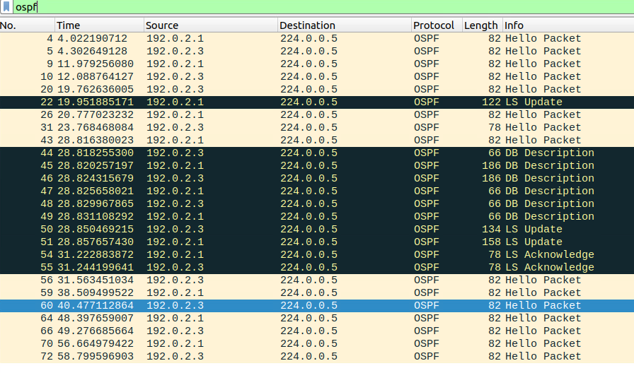
Note that there are no unicasts being sent.
What does the LSA look like when there are no IP addresses on the link? Let’s have a look:
Leaf1# show ip ospf data router 192.0.2.3 det
        OSPF Router with ID (192.0.2.3) (Process ID UNDERLAY VRF default)

                Router Link States (Area 0.0.0.0)

   LS age: 14
   Options: 0x2 (No TOS-capability, No DC)
   LS Type: Router Links
   Link State ID: 192.0.2.3
   Advertising Router: 192.0.2.3
   LS Seq Number: 0x800000c8
   Checksum: 0x03ec
   Length: 72
    Number of links: 4

     Link connected to: a Stub Network
      (Link ID) Network/Subnet Number: 192.0.2.3
      (Link Data) Network Mask: 255.255.255.255
       Number of TOS metrics: 0
         TOS   0 Metric: 1

     Link connected to: a Router (point-to-point)
     (Link ID) Neighboring Router ID: 192.0.2.1
     (Link Data) Router Interface address: 0.0.0.2
       Number of TOS metrics: 0
         TOS   0 Metric: 40

     Link connected to: a Router (point-to-point)
     (Link ID) Neighboring Router ID: 192.0.2.2
     (Link Data) Router Interface address: 0.0.0.3
       Number of TOS metrics: 0
         TOS   0 Metric: 40

     Link connected to: a Stub Network
      (Link ID) Network/Subnet Number: 203.0.113.1
      (Link Data) Network Mask: 255.255.255.255
       Number of TOS metrics: 0
         TOS   0 Metric: 1
The stub network in the beginning is the loopback being advertised. Then the two point to point interfaces towards the spines. Note that the Link ID is the RID of the neighbor and that the Link Data is a strange looking interface address. What does 0.0.0.2 mean? Since there is no IP configured, this is the ID of the interface. From the RFC:
For point-to-point interfaces, one or more link
descriptions are added to the router-LSA as follows:
o If the neighboring router is fully adjacent, add a
Type 1 link (point-to-point). The Link ID should be
set to the Router ID of the neighboring router. For
numbered point-to-point networks, the Link Data
should specify the IP interface address. For
unnumbered point-to-point networks, the Link Data
field should specify the interface’s MIB-II [Ref8]
ifIndex value. The cost should be set to the output
cost of the point-to-point interface.
This can be confirmed below:
Leaf1# show ip ospf int eth1/1
 Ethernet1/1 is up, line protocol is up
    Unnumbered interface using IP address of loopback0 (192.0.2.3)
    Process ID UNDERLAY VRF default, area 0.0.0.0
    Enabled by interface configuration
    State P2P, Network type P2P, cost 40
    Index 2, Transmit delay 1 sec
    1 Neighbors, flooding to 1, adjacent with 1
    Timer intervals: Hello 10, Dead 40, Wait 40, Retransmit 5
      Hello timer due in 00:00:04
    No authentication
    Number of opaque link LSAs: 0, checksum sum 0
    Interface ospf state change count: 36
Note that the index says 2. This mapping of RID to interface is important as the router must know what next-hops are available via what interface. This can be confirmed via the OSPF neighbor table:
Leaf1# show ip ospf nei 192.0.2.1 detail
 Neighbor Spine1, interface address 192.0.2.1
    Process ID UNDERLAY VRF default, in area 0.0.0.0 via interface Ethernet1/1
    State is FULL, 4 state changes, last change 00:05:13
    Hello options 0x2, dbd options 0x42
    Last non-hello packet received 00:05:11
      Dead timer due in 00:00:35
Let’s then look at a route:
Leaf1# show ip route 203.0.113.2/32
IP Route Table for VRF "default"
'*' denotes best ucast next-hop
'**' denotes best mcast next-hop
'[x/y]' denotes [preference/metric]
'%<string>' in via output denotes VRF <string>

203.0.113.2/32, ubest/mbest: 2/0
    *via 192.0.2.1, Eth1/1, [110/81], 00:09:48, ospf-UNDERLAY, intra
    *via 192.0.2.2, Eth1/2, [110/81], 1d22h, ospf-UNDERLAY, intra
The next-hops are the spines as expected. Then let’s look at the router for 192.0.2.1:
Leaf1# show ip route 192.0.2.1
IP Route Table for VRF "default"
'*' denotes best ucast next-hop
'**' denotes best mcast next-hop
'[x/y]' denotes [preference/metric]
'%<string>' in via output denotes VRF <string>

192.0.2.1/32, ubest/mbest: 1/0
    *via 192.0.2.1, Eth1/1, [110/41], 00:10:21, ospf-UNDERLAY, intra
     via 192.0.2.1, Eth1/1, [250/0], 00:09:59, am
This is where it gets really strange. 192.0.2.1 is available via…192.0.2.1! Note that it lists Eth1/1 as the outgoing interface which is what is important here. This is information that we derived from OSPF.
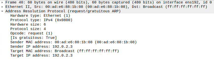
There is still one piece missing before we can send unicast packets. The routers must know what MAC addresses to encapsulate frames in, as I alluded to in the beginning. This is done via ARP as expected. On NX-OS, when an interface first comes up, it will generate Gratuitous ARP (GARP) frames as can be seen below:
arp: arp_send_gratuitous_internal: Sending GARP: IP=192.0.2.3, Interface=Ethernet1/1, SrcMAC=00ad.e688.1b08
arp: (Context=1) Sending packet on  with exclude phyIOD=5(Ethernet1/1), packetPrio=0, hrdType=0x1, hrdLen=6, protType=0x800, protLen=4, opcode=1, packetSize=28
arp: srcMAC=00ad.e688.1b08, srcIP=192.0.2.3, destMAC=ffff.ffff.ffff, destIP=192.0.2.3
GARP however is not used to populate the ARP cache UNLESS there is already an entry. It does not create new entries based on GARP. Below is an example of GARP:
To populate the ARP cache, a normal ARP request is generated as can be seen below:
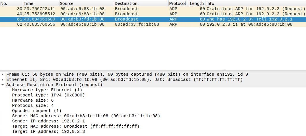
ARP cache is shown below:
Leaf1# show ip arp

Flags: * - Adjacencies learnt on non-active FHRP router
       + - Adjacencies synced via CFSoE
       # - Adjacencies Throttled for Glean
       CP - Added via L2RIB, Control plane Adjacencies
       PS - Added via L2RIB, Peer Sync
       RO - Re-Originated Peer Sync Entry
       D - Static Adjacencies attached to down interface

IP ARP Table for context default
Total number of entries: 2
Address         Age       MAC Address     Interface       Flags
192.0.2.1       00:17:29  00ad.b3fd.1b08  Ethernet1/1
192.0.2.2       00:10:05  00ad.7b30.1b08  Ethernet1/2
The MAC to use can also be seen in the forwarding table:
Leaf1# show forwarding adjacency 192.0.2.1

slot  1
=======


IPv4 adjacency information

next-hop         rewrite info    interface
-------------- --------------- -------------
192.0.2.1       00ad.b3fd.1b08 Ethernet1/1
The source MAC of frame will be that of the outgoing interface:
Leaf1# show int eth1/1 | i address
  Hardware: 100/1000/10000 Ethernet, address: 00ad.e688.1b08 (bia 00ad.e688.0101)
Let’s try a ping to confirm:
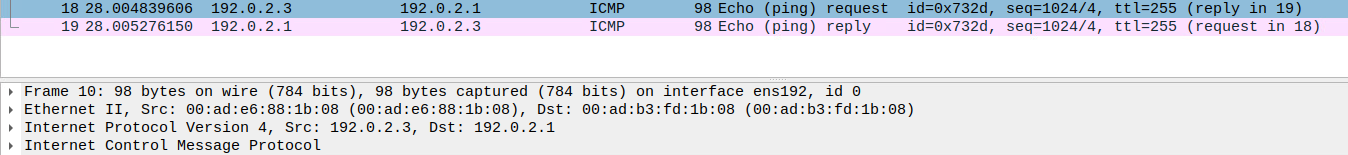
The expected MAC addresses are seen.
This is a lot to grasp! Let’s try to summarize:
- When using OSPF with unnumbered links, point to point network type is required.
- Point to point network type ignores the requirement for routers to be on the same subnet with the same network mask.
- OSPF packets are sent as multicast.
- Because the interface has no IP, in the router LSA the link is described using its interface ID.
- There is a mapping between the interface ID and the neighbor on that link which is maintained in the neighbor table.
- An interface coming up sends GARP to notify what MAC it is using.
- GARP is not used to populate the ARP cache unless there is already an entry.
- The routers send ARP requests to find the MAC address.
- Loopbacks do not have MAC addresses. MAC addresses of outgoing interface is used.
- Frames are encapsulated with source MAC of outgoing interface and destination MAC of receiving interface where OSPF neighbor is known.
I hope you have enjoyed this deep dive. Running unnumbered links is common but there is not a lot of documentation describing behind the scenes. See you in the next post!
Hi Daniel
Thanks for sharing this post💪
Would you consider putting the topology you use in the post?
That would make it easier to follow for “visual” people like me.
Hi Daniel,
This is a great post!
Jerome
Thanks buddy!
You have a talent to make a very complex topic look very simple. Your article has all that is required to cover the topic but nothing extra that would distract from the topic. The precision and attention to detail reminds me of articles from INE/Lapukhov a decade ago.
Thank you!
Thank you!
Hey Daniel.
nice level of detail in this one and helped to piece it all together with a good flow.
Many thanks!
thank you ,
I configured 3 router each one with a loopback address , 1.1.1.1 2.2.2.2 3.3.3.3 and connection between them is using ethernet interface in P2P mode an unnumbred ip to the loopck , the ospf was configured corectly and all the loopback are in the routing table of each router . when i ping from router R1 it arrive to Router R3 via R2 but R3 doesn’t answer , the same when i ping from R3 to R1 the ping arrive to R1 via R2 but R1 doesn’t answer ?
What are you sourcing the ping from? The loopback? Make sure you have the correct source interface/IP and that there is a return route to get back.