As I dive into the world of VXLAN, I will need a lab as that is the best way to deepen the learning process and to get hands-on experience with a protocol. I will be building a Cisco Nexus9000v lab in VMware ESX but the same images can be used in CML, EveNG, GNS3, etc. The lab is based on the following topology:
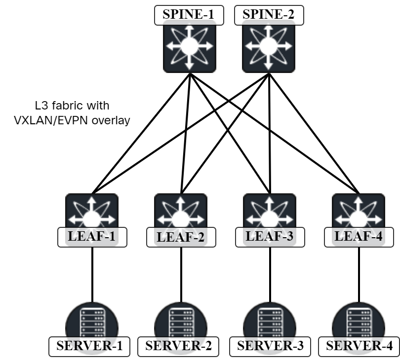
The specific platform I’ll use is the Nexus9300v which has the following requirements:
- 1 vCPU (2 recommended).
- 10 GB of RAM (12 GB recommended).
Note that there is also a Nexus9500v image which is a 16-slot modular chassis. As I have no need for multiple slots, and it requires more CPUs, I will not be using this image.
The specific image I am using is nexus9300v64.10.2.5.M.ova, which is NX-OS version 10.2.5.
Deploying the OVA can take some time but is otherwise straightforward. Refer to my post on caveats for more details.
I have mapped the different NICs to different port groups:
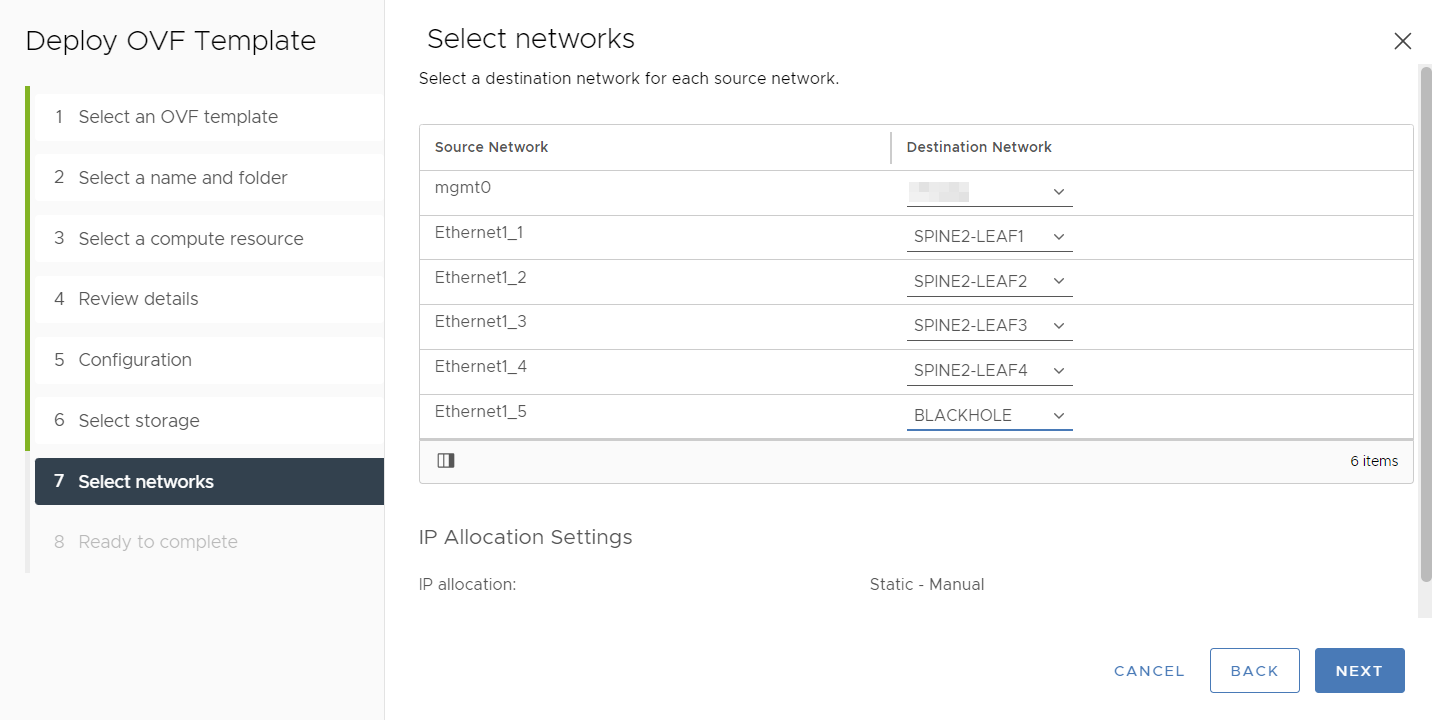
The mgmt0 interface is mapped to my management network so that I can SSH to the devices. I have also created specific port groups for the interconnections between leaf and spine switches. Interfaces that I don’t intend to use have been mapped to a port group I’m not using named Blackhole. If you are setting this up in something like CML, you could just use the GUI to connect the devices.
The lab will have the following characteristics:
- All links are unnumbered from a loopback.
- A dedicated loopback is used for VXLAN.
- Flood and learn using PIM ASM and Anycast RP (no EVPN).
- OSPF as IGP in underlay.
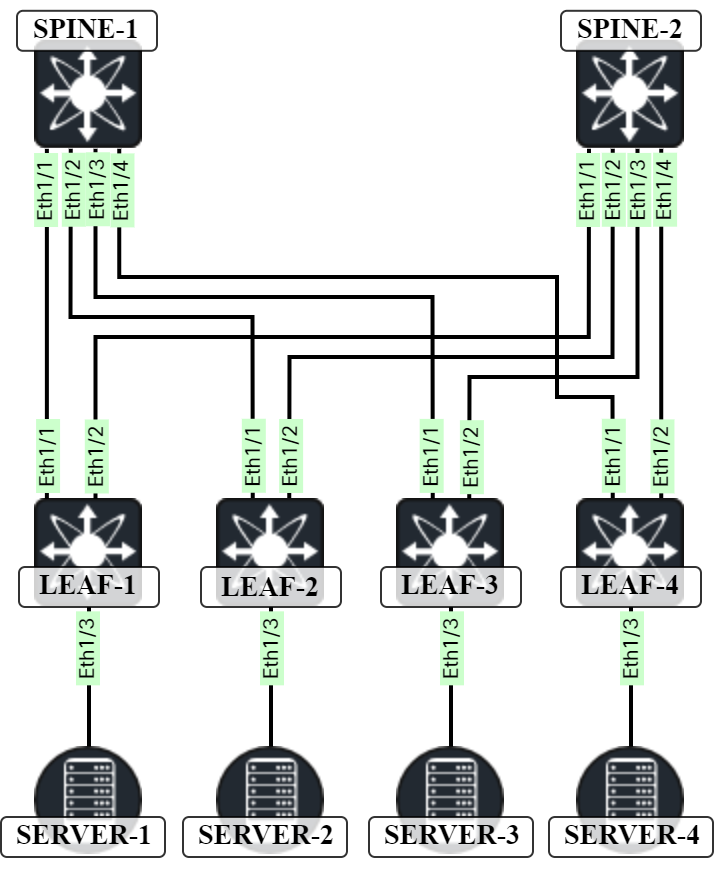
The physical topology will look like this:
First, on the spine nodes, let’s verify everything is connected as intended:
Spine1# sh cdp nei
Capability Codes: R - Router, T - Trans-Bridge, B - Source-Route-Bridge
                  S - Switch, H - Host, I - IGMP, r - Repeater,
                  V - VoIP-Phone, D - Remotely-Managed-Device,
                  s - Supports-STP-Dispute

Device-ID          Local Intrfce  Hldtme Capability  Platform      Port ID
Leaf1(9KNJLVLQARV)
                    Eth1/1         138    R S s     N9K-C9300v    Eth1/1
Leaf2(9F7B5I069T7)
                    Eth1/2         121    R S I s   N9K-C9300v    Eth1/1
Leaf3(9420O7O0H6B)
                    Eth1/3         169    R S I s   N9K-C9300v    Eth1/1
Leaf4(9RYA5FLIOR8)
                    Eth1/4         155    R S I s   N9K-C9300v    Eth1/1
Spine2# sh cdp nei
Capability Codes: R - Router, T - Trans-Bridge, B - Source-Route-Bridge
                  S - Switch, H - Host, I - IGMP, r - Repeater,
                  V - VoIP-Phone, D - Remotely-Managed-Device,
                  s - Supports-STP-Dispute

Device-ID          Local Intrfce  Hldtme Capability  Platform      Port ID
Leaf1(9KNJLVLQARV)
                    Eth1/1         174    R S s     N9K-C9300v    Eth1/2
Leaf2(9F7B5I069T7)
                    Eth1/2         157    R S I s   N9K-C9300v    Eth1/2
Leaf3(9420O7O0H6B)
                    Eth1/3         145    R S I s   N9K-C9300v    Eth1/2
Leaf4(9RYA5FLIOR8)
                    Eth1/4         138    R S I s   N9K-C9300v    Eth1/2
Interfaces are connected according to our physical topology.
Next, we will turn the ports into routed ports and enable jumbo frames:
Spine1(config)# int eth1/1-4
Spine1(config-if-range)# mtu 9216
Spine1(config-if-range)# no switchport

Spine2(config)# int eth1/1-4
Spine2(config-if-range)# mtu 9216
Spine2(config-if-range)# no switchport

Leaf1(config)# int eth1/1-2
Leaf1(config-if-range)# mtu 9216
Leaf1(config-if-range)# no switchport

Leaf2(config)# int eth1/1-2
Leaf2(config-if-range)# mtu 9216
Leaf2(config-if-range)# no switchport

Leaf3(config)# int eth1/1-2
Leaf3(config-if-range)# mtu 9216
Leaf3(config-if-range)# no switchport

Leaf4(config)# int eth1/1-2
Leaf4(config-if-range)# mtu 9216
Leaf4(config-if-range)# no switchport
Next, the underlay will be configured using OSPF on unnumbered links according to this topology:
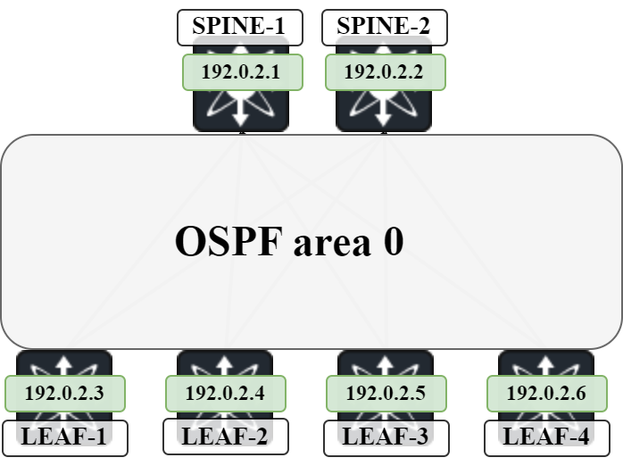
To do this, the following is needed:
- Enable feature OSPF.
- Add loopbacks to all devices.
- Configure Ethernet interfaces as point to point.
- Configure Ethernet interfaces as unnumbered to loopback0.
- Enable OSPF on Ethernet interfaces and loopbacks.
In addition, we will also configure name lookup in OSPF to get the name of our OSPF neighbors when verifying adjacencies.
Spine1(config)# feature ospf
Spine1(config)# ip host Leaf1 192.0.2.3
Spine1(config)# ip host Leaf2 192.0.2.4
Spine1(config)# ip host Leaf3 192.0.2.5
Spine1(config)# ip host Leaf4 192.0.2.6
Spine1(config)# int lo0
Spine1(config-if)# ip add 192.0.2.1/32
Spine1(config-if)# ip router ospf UNDERLAY area 0.0.0.0
Spine1(config-if)# int eth1/1-4
Spine1(config-if-range)# medium p2p
Spine1(config-if-range)# ip unnumbered lo0
Spine1(config-if-range)# ip ospf network point-to-point
Spine1(config-if-range)# ip router ospf UNDERLAY area 0.0.0.0
Spine1(config-if-range)# router ospf UNDERLAY
Spine1(config-router)# log-adjacency-changes detail
Spine1(config-router)# name-lookup

Spine2(config)# feature ospf
Spine2(config)# ip host Leaf1 192.0.2.3
Spine2(config)# ip host Leaf2 192.0.2.4
Spine2(config)# ip host Leaf3 192.0.2.5
Spine2(config)# ip host Leaf4 192.0.2.6
Spine2(config)# int lo0
Spine2(config-if)#  ip add 192.0.2.2/32
Spine2(config-if)#  ip router ospf UNDERLAY area 0.0.0.0
Spine2(config-if)# int eth1/1-4
Spine2(config-if-range)#  medium p2p
Spine2(config-if-range)#  ip unnumbered lo0
Spine2(config-if-range)#  ip ospf network point-to-point
Spine2(config-if-range)#  ip router ospf UNDERLAY area 0.0.0.0
Spine2(config-if-range)# router ospf UNDERLAY
Spine2(config-router)#  log-adjacency-changes detail
Spine2(config-router)#  name-lookup

Leaf1(config)# feature ospf
Leaf1(config)# ip host Spine1 192.0.2.1
Leaf1(config)# ip host Spine2 192.0.2.2
Leaf1(config)# int lo0
Leaf1(config-if)#  ip add 192.0.2.3/32
Leaf1(config-if)#  ip router ospf UNDERLAY area 0.0.0.0
Leaf1(config-if)# int eth1/1-2
Leaf1(config-if-range)#  medium p2p
Leaf1(config-if-range)#  ip unnumbered lo0
Leaf1(config-if-range)#  ip ospf network point-to-point
Leaf1(config-if-range)#  ip router ospf UNDERLAY area 0.0.0.0
Leaf1(config-if-range)# router ospf UNDERLAY
Leaf1(config-router)#  log-adjacency-changes detail
Leaf1(config-router)#  name-lookup

Leaf2(config)# feature ospf
Leaf2(config)# ip host Spine1 192.0.2.1
Leaf2(config)# ip host Spine2 192.0.2.2
Leaf2(config)# int lo0
Leaf2(config-if)#  ip add 192.0.2.4/32
Leaf2(config-if)#  ip router ospf UNDERLAY area 0.0.0.0
Leaf2(config-if)# int eth1/1-2
Leaf2(config-if-range)#  medium p2p
Leaf2(config-if-range)#  ip unnumbered lo0
Leaf2(config-if-range)#  ip ospf network point-to-point
Leaf2(config-if-range)#  ip router ospf UNDERLAY area 0.0.0.0
Leaf2(config-if-range)# router ospf UNDERLAY
Leaf2(config-router)#  log-adjacency-changes detail
Leaf2(config-router)#  name-lookup

Leaf3(config)# feature ospf
Leaf3(config)# ip host Spine1 192.0.2.1
Leaf3(config)# ip host Spine2 192.0.2.2
Leaf3(config)# int lo0
Leaf3(config-if)#  ip add 192.0.2.5/32
Leaf3(config-if)#  ip router ospf UNDERLAY area 0.0.0.0
Leaf3(config-if)# int eth1/1-2
Leaf3(config-if-range)#  medium p2p
Leaf3(config-if-range)#  ip unnumbered lo0
Leaf3(config-if-range)#  ip ospf network point-to-point
Leaf3(config-if-range)#  ip router ospf UNDERLAY area 0.0.0.0
Leaf3(config-if-range)# router ospf UNDERLAY
Leaf3(config-router)#  log-adjacency-changes detail
Leaf3(config-router)#  name-lookup

Leaf4(config)# feature ospf
Leaf4(config)# ip host Spine1 192.0.2.1
Leaf4(config)# ip host Spine2 192.0.2.2
Leaf4(config)# int lo0
Leaf4(config-if)#  ip add 192.0.2.6/32
Leaf4(config-if)#  ip router ospf UNDERLAY area 0.0.0.0
Leaf4(config-if)# int eth1/1-2
Leaf4(config-if-range)#  medium p2p
Leaf4(config-if-range)#  ip unnumbered lo0
Leaf4(config-if-range)#  ip ospf network point-to-point
Leaf4(config-if-range)#  ip router ospf UNDERLAY area 0.0.0.0
Leaf4(config-if-range)# router ospf UNDERLAY
Leaf4(config-router)#  log-adjacency-changes detail
Leaf4(config-router)#  name-lookup
At this stage I was going to start verifying OSPF but noticed that interfaces had been shutdown after they were converted to routed ports. Let’s bring them up again:
Spine1(config)# int eth1/1-4
Spine1(config-if-range)# no shut

Spine2(config)# int eth1/1-4
Spine2(config-if-range)# no shut

Leaf1(config)# int eth1/1-2
Leaf1(config-if-range)# no shut

Leaf2(config)# int eth1/1-2
Leaf2(config-if-range)# no shut

Leaf3(config)# int eth1/1-2
Leaf3(config-if-range)# no shut

Leaf4(config)# int eth1/1-2
Leaf4(config-if-range)# no shut
Let’s verify the OSPF adjacencies on the spines:
Spine1# show ip ospf nei
 OSPF Process ID UNDERLAY VRF default
 Total number of neighbors: 4
 Neighbor ID     Pri State            Up Time  Address         Interface
 Leaf1             1 FULL/ -          00:01:40 192.0.2.3       Eth1/1
 Leaf2             1 FULL/ -          00:01:16 192.0.2.4       Eth1/2
 Leaf3             1 FULL/ -          00:00:51 192.0.2.5       Eth1/3
 Leaf4             1 FULL/ -          00:02:38 192.0.2.6       Eth1/4

Spine2# show ip ospf nei
 OSPF Process ID UNDERLAY VRF default
 Total number of neighbors: 4
 Neighbor ID     Pri State            Up Time  Address         Interface
 Leaf1             1 FULL/ -          00:02:05 192.0.2.3       Eth1/1
 Leaf2             1 FULL/ -          00:01:26 192.0.2.4       Eth1/2
 Leaf3             1 FULL/ -          00:01:13 192.0.2.5       Eth1/3
 Leaf4             1 FULL/ -          00:02:27 192.0.2.6       Eth1/4
Due to the name lookup, we now get a nice representation of OSPF adjacencies including the names. Let’s check what a Type 1 LSA looks like now that we are using unnumbered links:
Spine1# show ip ospf data router 192.0.2.3 det
        OSPF Router with ID (192.0.2.1) (Process ID UNDERLAY VRF default)

                Router Link States (Area 0.0.0.0)

   LS age: 626
   Options: 0x2 (No TOS-capability, No DC)
   LS Type: Router Links
   Link State ID: 192.0.2.3
   Advertising Router: Leaf1
   LS Seq Number: 0x80000004
   Checksum: 0x44bf
   Length: 60
    Number of links: 3

     Link connected to: a Stub Network
      (Link ID) Network/Subnet Number: 192.0.2.3
      (Link Data) Network Mask: 255.255.255.255
       Number of TOS metrics: 0
         TOS   0 Metric: 1

     Link connected to: a Router (point-to-point)
     (Link ID) Neighboring Router ID: 192.0.2.1
     (Link Data) Router Interface address: 0.0.0.2
       Number of TOS metrics: 0
         TOS   0 Metric: 40

     Link connected to: a Router (point-to-point)
     (Link ID) Neighboring Router ID: 192.0.2.2
     (Link Data) Router Interface address: 0.0.0.3
       Number of TOS metrics: 0
         TOS   0 Metric: 40
Due to using unnumbered links, the router interface address looks a bit strange in the type 1 LSA. What is 0.0.0.2 and 0.0.0.3. When in doubt, refer to what the RFC for OSPF (RFC 2328) says:
In addition, the Link Data field is specified for each link. This field gives 32 bits of extra information for the link. For links to transit networks, numbered point-to-point links and virtual links, this field specifies the IP interface address of the associated router interface (this is needed by the routing table calculation, see Section 16.1.1). For links to stub networks, this field specifies the stub network’s IP address mask. For unnumbered point-to-point links, the Link Data field should be set to the unnumbered interface’s MIB-II [Ref8] ifIndex value.
The strange looking IP that we see is simply the index of the interface. This can be confirmed on Leaf1:
Leaf1# show ip ospf interface
 Ethernet1/1 is up, line protocol is up
    Unnumbered interface using IP address of loopback0 (192.0.2.3)
    Process ID UNDERLAY VRF default, area 0.0.0.0
    Enabled by interface configuration
    State P2P, Network type P2P, cost 40
    Index 2, Transmit delay 1 sec
    1 Neighbors, flooding to 1, adjacent with 1
    Timer intervals: Hello 10, Dead 40, Wait 40, Retransmit 5
      Hello timer due in 00:00:07
    No authentication
    Number of opaque link LSAs: 0, checksum sum 0
    Interface ospf state change count: 1
 Ethernet1/2 is up, line protocol is up
    Unnumbered interface using IP address of loopback0 (192.0.2.3)
    Process ID UNDERLAY VRF default, area 0.0.0.0
    Enabled by interface configuration
    State P2P, Network type P2P, cost 40
    Index 3, Transmit delay 1 sec
    1 Neighbors, flooding to 1, adjacent with 1
    Timer intervals: Hello 10, Dead 40, Wait 40, Retransmit 5
      Hello timer due in 00:00:07
    No authentication
    Number of opaque link LSAs: 0, checksum sum 0
    Interface ospf state change count: 1
 loopback0 is up, line protocol is up
    IP address 192.0.2.3/32
    Process ID UNDERLAY VRF default, area 0.0.0.0
    Enabled by interface configuration
    State LOOPBACK, Network type LOOPBACK, cost 1
    Index 1
Let’s see if we have any routes in OSPF:
Leaf1# show ip route ospf
IP Route Table for VRF "default"
'*' denotes best ucast next-hop
'**' denotes best mcast next-hop
'[x/y]' denotes [preference/metric]
'%<string>' in via output denotes VRF <string>

192.0.2.1/32, ubest/mbest: 1/0
    *via 192.0.2.1, Eth1/1, [110/41], 00:28:11, ospf-UNDERLAY, intra
192.0.2.2/32, ubest/mbest: 1/0
    *via 192.0.2.2, Eth1/2, [110/41], 00:28:13, ospf-UNDERLAY, intra
192.0.2.4/32, ubest/mbest: 2/0
    *via 192.0.2.1, Eth1/1, [110/81], 00:27:40, ospf-UNDERLAY, intra
    *via 192.0.2.2, Eth1/2, [110/81], 00:27:39, ospf-UNDERLAY, intra
192.0.2.5/32, ubest/mbest: 2/0
    *via 192.0.2.1, Eth1/1, [110/81], 00:27:15, ospf-UNDERLAY, intra
    *via 192.0.2.2, Eth1/2, [110/81], 00:27:21, ospf-UNDERLAY, intra
192.0.2.6/32, ubest/mbest: 2/0
    *via 192.0.2.1, Eth1/1, [110/81], 00:28:11, ospf-UNDERLAY, intra
    *via 192.0.2.2, Eth1/2, [110/81], 00:28:13, ospf-UNDERLAY, intra
Notice the ECMP paths towards the other leafs. Let’s see if we can ping:
Leaf1# ping 192.0.2.1
PING 192.0.2.1 (192.0.2.1): 56 data bytes
64 bytes from 192.0.2.1: icmp_seq=0 ttl=254 time=2.109 ms
64 bytes from 192.0.2.1: icmp_seq=1 ttl=254 time=1.367 ms
64 bytes from 192.0.2.1: icmp_seq=2 ttl=254 time=1.375 ms
64 bytes from 192.0.2.1: icmp_seq=3 ttl=254 time=1.127 ms
64 bytes from 192.0.2.1: icmp_seq=4 ttl=254 time=1.117 ms

--- 192.0.2.1 ping statistics ---
5 packets transmitted, 5 packets received, 0.00% packet loss
round-trip min/avg/max = 1.117/1.419/2.109 ms
Leaf1# ping 192.0.2.2
PING 192.0.2.2 (192.0.2.2): 56 data bytes
64 bytes from 192.0.2.2: icmp_seq=0 ttl=254 time=1.814 ms
64 bytes from 192.0.2.2: icmp_seq=1 ttl=254 time=2.444 ms
64 bytes from 192.0.2.2: icmp_seq=2 ttl=254 time=1.276 ms
64 bytes from 192.0.2.2: icmp_seq=3 ttl=254 time=1.181 ms
64 bytes from 192.0.2.2: icmp_seq=4 ttl=254 time=1.137 ms

--- 192.0.2.2 ping statistics ---
5 packets transmitted, 5 packets received, 0.00% packet loss
round-trip min/avg/max = 1.137/1.57/2.444 ms
Leaf1# ping 192.0.2.4
PING 192.0.2.4 (192.0.2.4): 56 data bytes
64 bytes from 192.0.2.4: icmp_seq=0 ttl=253 time=3.575 ms
64 bytes from 192.0.2.4: icmp_seq=1 ttl=253 time=2.881 ms
64 bytes from 192.0.2.4: icmp_seq=2 ttl=253 time=2.072 ms
64 bytes from 192.0.2.4: icmp_seq=3 ttl=253 time=2.089 ms
64 bytes from 192.0.2.4: icmp_seq=4 ttl=253 time=2.065 ms

--- 192.0.2.4 ping statistics ---
5 packets transmitted, 5 packets received, 0.00% packet loss
round-trip min/avg/max = 2.065/2.536/3.575 ms
Leaf1# ping 192.0.2.5
PING 192.0.2.5 (192.0.2.5): 56 data bytes
64 bytes from 192.0.2.5: icmp_seq=0 ttl=253 time=4.721 ms
64 bytes from 192.0.2.5: icmp_seq=1 ttl=253 time=3.019 ms
64 bytes from 192.0.2.5: icmp_seq=2 ttl=253 time=2.208 ms
64 bytes from 192.0.2.5: icmp_seq=3 ttl=253 time=3.045 ms
64 bytes from 192.0.2.5: icmp_seq=4 ttl=253 time=3.29 ms

--- 192.0.2.5 ping statistics ---
5 packets transmitted, 5 packets received, 0.00% packet loss
round-trip min/avg/max = 2.208/3.256/4.721 ms
Leaf1# ping 192.0.2.6
PING 192.0.2.6 (192.0.2.6): 56 data bytes
64 bytes from 192.0.2.6: icmp_seq=0 ttl=253 time=4.004 ms
64 bytes from 192.0.2.6: icmp_seq=1 ttl=253 time=2.198 ms
64 bytes from 192.0.2.6: icmp_seq=2 ttl=253 time=2.094 ms
64 bytes from 192.0.2.6: icmp_seq=3 ttl=253 time=2.057 ms
64 bytes from 192.0.2.6: icmp_seq=4 ttl=253 time=2.095 ms

--- 192.0.2.6 ping statistics ---
5 packets transmitted, 5 packets received, 0.00% packet loss
round-trip min/avg/max = 2.057/2.489/4.004 ms
The underlay is now working. Let’s add an additional loopback that will be used for VXLAN:
Leaf1(config)# int lo1
Leaf1(config-if)# ip add 203.0.113.1/32
Leaf1(config-if)# ip router ospf UNDERLAY area 0.0.0.0

Leaf2(config)# int lo1
Leaf2(config-if)# ip add 203.0.113.2/32
Leaf2(config-if)# ip router ospf UNDERLAY area 0.0.0.0

Leaf3(config)# int lo1
Leaf3(config-if)# ip add 203.0.113.3/32
Leaf3(config-if)# ip router ospf UNDERLAY area 0.0.0.0

Leaf4(config)# int lo1
Leaf4(config-if)# ip add 203.0.113.4/32
Leaf4(config-if)# ip router ospf UNDERLAY area 0.0.0.0
Now, let’s verify the loopbacks are reachable:
Leaf1# ping 203.0.113.2 source-interface lo1
PING 203.0.113.2 (203.0.113.2): 56 data bytes
64 bytes from 203.0.113.2: icmp_seq=0 ttl=253 time=4.443 ms
64 bytes from 203.0.113.2: icmp_seq=1 ttl=253 time=2.555 ms
64 bytes from 203.0.113.2: icmp_seq=2 ttl=253 time=2.489 ms
64 bytes from 203.0.113.2: icmp_seq=3 ttl=253 time=2.85 ms
64 bytes from 203.0.113.2: icmp_seq=4 ttl=253 time=2.689 ms

--- 203.0.113.2 ping statistics ---
5 packets transmitted, 5 packets received, 0.00% packet loss
round-trip min/avg/max = 2.489/3.005/4.443 ms
Leaf1# ping 203.0.113.3 source-interface lo1
PING 203.0.113.3 (203.0.113.3): 56 data bytes
64 bytes from 203.0.113.3: icmp_seq=0 ttl=253 time=6.35 ms
64 bytes from 203.0.113.3: icmp_seq=1 ttl=253 time=3.259 ms
64 bytes from 203.0.113.3: icmp_seq=2 ttl=253 time=2.675 ms
64 bytes from 203.0.113.3: icmp_seq=3 ttl=253 time=2.398 ms
64 bytes from 203.0.113.3: icmp_seq=4 ttl=253 time=2.704 ms

--- 203.0.113.3 ping statistics ---
5 packets transmitted, 5 packets received, 0.00% packet loss
round-trip min/avg/max = 2.398/3.477/6.35 ms
Leaf1# ping 203.0.113.4 source-interface lo1
PING 203.0.113.4 (203.0.113.4): 56 data bytes
64 bytes from 203.0.113.4: icmp_seq=0 ttl=253 time=3.81 ms
64 bytes from 203.0.113.4: icmp_seq=1 ttl=253 time=2.244 ms
64 bytes from 203.0.113.4: icmp_seq=2 ttl=253 time=1.958 ms
64 bytes from 203.0.113.4: icmp_seq=3 ttl=253 time=2.217 ms
64 bytes from 203.0.113.4: icmp_seq=4 ttl=253 time=2.237 ms

--- 203.0.113.4 ping statistics ---
5 packets transmitted, 5 packets received, 0.00% packet loss
round-trip min/avg/max = 1.958/2.493/3.81 ms
The next step is to enable PIM ASM and run Anycast RP on the spines to be able to send the multidestination traffic over multicast. We want to achieve the following:
- Enable the PIM feature.
- Enable PIM on all the underlay links.
- Create new loopback on spines to be used for Anycast RP.
- Advertise this loopback into OSPF.
- Configure Anycast RP (Nexus feature) on spines.
- Configure the RP on all devices.
Spine1(config)# feature pim
Spine1(config)# interface loopback1
Spine1(config-if)# ip add 192.0.2.255/32
Spine1(config-if)# ip pim sparse-mode
Spine1(config-if)# ip router ospf UNDERLAY area 0.0.0.0
Spine1(config-if)# int lo0
Spine1(config-if)# ip pim sparse-mode
Spine1(config-if)# int ethernet1/1-4
Spine1(config-if-range)# ip pim sparse-mode
Spine1(config-if-range)# ip pim rp-address 192.0.2.255 group-list 224.0.0.0/4
Spine1(config)# ip pim anycast-rp 192.0.2.255 192.0.2.1
Spine1(config)# ip pim anycast-rp 192.0.2.255 192.0.2.2

Spine2(config)# feature pim
Spine2(config)# interface loopback1
Spine2(config-if)# ip add 192.0.2.255/32
Spine2(config-if)# ip pim sparse-mode
Spine2(config-if)# ip router ospf UNDERLAY area 0.0.0.0
Spine2(config-if)# int lo0
Spine2(config-if)# ip pim sparse-mode
Spine2(config-if)# int ethernet1/1-4
Spine2(config-if-range)# ip pim sparse-mode
Spine2(config-if-range)# ip pim rp-address 192.0.2.255 group-list 224.0.0.0/4
Spine2(config)# ip pim anycast-rp 192.0.2.255 192.0.2.1
Spine2(config)# ip pim anycast-rp 192.0.2.255 192.0.2.2

Leaf1(config)# feature pim
Leaf1(config)# ip pim rp-address 192.0.2.255 group-list 224.0.0.0/4
Leaf1(config)# interface ethernet1/1-2
Leaf1(config-if-range)#  ip pim sparse-mode

Leaf2(config)# feature pim
Leaf2(config)# ip pim rp-address 192.0.2.255 group-list 224.0.0.0/4
Leaf2(config)# interface ethernet1/1-2
Leaf2(config-if-range)#  ip pim sparse-mode

Leaf3(config)# feature pim
Leaf3(config)# ip pim rp-address 192.0.2.255 group-list 224.0.0.0/4
Leaf3(config)# interface ethernet1/1-2
Leaf3(config-if-range)#  ip pim sparse-mode

Leaf4(config)# feature pim
Leaf4(config)# ip pim rp-address 192.0.2.255 group-list 224.0.0.0/4
Leaf4(config)# interface ethernet1/1-2
Leaf4(config-if-range)#  ip pim sparse-mode
Verify PIM neighborships and that the RP has been configured:
Spine1# show ip pim nei
PIM Neighbor Status for VRF "default"
Neighbor        Interface            Uptime    Expires   DR       Bidir-  BFD    ECMP Redirect
                                                         Priority Capable State     Capable
192.0.2.3       Ethernet1/1          16:31:57  00:01:26  1        yes     n/a     no
192.0.2.4       Ethernet1/2          00:03:18  00:01:22  1        yes     n/a     no
192.0.2.5       Ethernet1/3          00:01:48  00:01:26  1        yes     n/a     no
192.0.2.6       Ethernet1/4          00:00:42  00:01:34  1        yes     n/a     no
Spine1# show ip pim rp
PIM RP Status Information for VRF "default"
BSR disabled
Auto-RP disabled
BSR RP Candidate policy: None
BSR RP policy: None
Auto-RP Announce policy: None
Auto-RP Discovery policy: None

Anycast-RP 192.0.2.255 members:
  192.0.2.1*  192.0.2.2

RP: 192.0.2.255*, (0),
 uptime: 16:38:37   priority: 255,
 RP-source: (local),
 group ranges:
 224.0.0.0/4
Notice that list of Anycast RP members. Don’t forget to also put PIM on the loopback to be used for VXLAN:
Leaf1(config)# int lo1
Leaf1(config-if)# ip pim sparse-mode

Leaf2(config)# int lo1
Leaf2(config-if)# ip pim sparse-mode

Leaf3(config)# int lo1
Leaf3(config-if)# ip pim sparse-mode

Leaf4(config)# int lo1
Leaf4(config-if)# ip pim sparse-mode
Now, it’s time to start with the VXLAN configuration. We want to configure the following on the leafs:
- Enable VXLAN feature.
- Enable feature to map VLANs to VNIs.
- Create Network Virtual Endpoint (NVE).
Configure port towards server.
First, enable the VXLAN feature:
Leaf1(config)# feature vn-segment-vlan-based
Leaf1(config)# feature nv overlay

Leaf2(config)# feature vn-segment-vlan-based
Leaf2(config)# feature nv overlay

Leaf3(config)# feature vn-segment-vlan-based
Leaf3(config)# feature nv overlay

Leaf4(config)# feature vn-segment-vlan-based
Leaf4(config)# feature nv overlay
Then configure the NVE and map it to a multicast group such as 239.0.0.1:
Leaf1(config)# interface nve1
Leaf1(config-if-nve)#   no shutdown
Leaf1(config-if-nve)#   source-interface loopback1
Leaf1(config-if-nve)#   member vni 1000
Leaf1(config-if-nve-vni)#     mcast-group 239.0.0.1

Leaf2(config)# interface nve1
Leaf2(config-if-nve)#   no shutdown
Leaf2(config-if-nve)#   source-interface loopback1
Leaf2(config-if-nve)#   member vni 1000
Leaf2(config-if-nve-vni)#     mcast-group 239.0.0.1

Leaf3(config)# interface nve1
Leaf3(config-if-nve)#   no shutdown
Leaf3(config-if-nve)#   source-interface loopback1
Leaf3(config-if-nve)#   member vni 1000
Leaf3(config-if-nve-vni)#     mcast-group 239.0.0.1

Leaf4(config)# interface nve1
Leaf4(config-if-nve)#   no shutdown
Leaf4(config-if-nve)#   source-interface loopback1
Leaf4(config-if-nve)#   member vni 1000
Leaf4(config-if-nve-vni)#     mcast-group 239.0.0.1
Verify that NVE is up:
Leaf1# show int nve1
nve1 is up
admin state is up,  Hardware: NVE
  MTU 9216 bytes
  Encapsulation VXLAN
  Auto-mdix is turned off
  RX
    ucast: 46 pkts, 3634 bytes - mcast: 2 pkts, 165 bytes
  TX
    ucast: 67 pkts, 8300 bytes - mcast: 0 pkts, 0 bytes
Configure the VLAN, map it to the VNI, and configure the port towards the server:
Leaf1(config)# vlan 100
Leaf1(config-vlan)#  vn-segment 1000
Leaf1(config-vlan)# interface ethernet1/3
Warning: Enable double-wide arp-ether tcam carving if igmp snooping/Hsrp over vxlan is enabled. Ignore if tcam carving is already configured.
Leaf1(config-if)#  switchport mode access
Leaf1(config-if)#  switchport access vlan 100
Leaf1(config-if)#  no shutdown

Leaf2(config)# vlan 100
Leaf2(config-vlan)#  vn-segment 1000
Leaf2(config-vlan)# interface ethernet1/3
Warning: Enable double-wide arp-ether tcam carving if igmp snooping/Hsrp over vxlan is enabled. Ignore if tcam carving is already configured.
Leaf2(config-if)#  switchport mode access
Leaf2(config-if)#  switchport access vlan 100
Leaf2(config-if)#  no shutdown

Leaf3(config)# vlan 100
Leaf3(config-vlan)#  vn-segment 1000
Leaf3(config-vlan)# interface ethernet1/3
Warning: Enable double-wide arp-ether tcam carving if igmp snooping/Hsrp over vxlan is enabled. Ignore if tcam carving is already configured.
Leaf3(config-if)#  switchport mode access
Leaf3(config-if)#  switchport access vlan 100
Leaf3(config-if)#  no shutdown

Leaf4(config)# vlan 100
Leaf4(config-vlan)#  vn-segment 1000
Leaf4(config-vlan)# interface ethernet1/3
Warning: Enable double-wide arp-ether tcam carving if igmp snooping/Hsrp over vxlan is enabled. Ignore if tcam carving is already configured.
Leaf4(config-if)#  switchport mode access
Leaf4(config-if)#  switchport access vlan 100
Leaf4(config-if)#  no shutdown
At this point the leafs will join the multicast group:
Spine1# show ip mroute
IP Multicast Routing Table for VRF "default"

(*, 232.0.0.0/8), uptime: 00:01:14, pim ip
  Incoming interface: Null, RPF nbr: 0.0.0.0
  Outgoing interface list: (count: 0)


(*, 239.0.0.1/32), uptime: 00:01:01, pim ip
  Incoming interface: loopback1, RPF nbr: 192.0.2.255
  Outgoing interface list: (count: 1)
    Ethernet1/2, uptime: 00:01:01, pim


(203.0.113.1/32, 239.0.0.1/32), uptime: 00:00:47, pim mrib ip
  Incoming interface: Ethernet1/1, RPF nbr: 192.0.2.3, internal
  Outgoing interface list: (count: 1)
    Ethernet1/2, uptime: 00:00:47, pim


(203.0.113.2/32, 239.0.0.1/32), uptime: 00:01:01, pim mrib ip
  Incoming interface: Ethernet1/2, RPF nbr: 192.0.2.4, internal
  Outgoing interface list: (count: 1)
    Ethernet1/2, uptime: 00:01:01, pim, (RPF)


(203.0.113.3/32, 239.0.0.1/32), uptime: 00:00:31, pim mrib ip
  Incoming interface: Ethernet1/3, RPF nbr: 192.0.2.5, internal
  Outgoing interface list: (count: 1)
    Ethernet1/2, uptime: 00:00:31, pim


(203.0.113.4/32, 239.0.0.1/32), uptime: 00:00:25, pim mrib ip
  Incoming interface: Ethernet1/4, RPF nbr: 192.0.2.6, internal
  Outgoing interface list: (count: 1)
    Ethernet1/2, uptime: 00:00:25, pim
There is now connectivity between the two servers:
cisco@server4:~$ ping 198.51.100.11
PING 198.51.100.11 (198.51.100.11) 56(84) bytes of data.
64 bytes from 198.51.100.11: icmp_seq=1 ttl=64 time=3.51 ms
64 bytes from 198.51.100.11: icmp_seq=2 ttl=64 time=4.39 ms
64 bytes from 198.51.100.11: icmp_seq=3 ttl=64 time=4.61 ms
^C
--- 198.51.100.11 ping statistics ---
3 packets transmitted, 3 received, 0% packet loss, time 2004ms
rtt min/avg/max/mdev = 3.509/4.170/4.612/0.476 ms
We can see on the leafs that they have learned the MAC address of the other server via the NVE:
Leaf1# show mac address-table
Legend:
        * - primary entry, G - Gateway MAC, (R) - Routed MAC, O - Overlay MAC
        age - seconds since last seen,+ - primary entry using vPC Peer-Link,
        (T) - True, (F) - False, C - ControlPlane MAC, ~ - vsan,
        (NA)- Not Applicable
   VLAN     MAC Address      Type      age     Secure NTFY Ports
---------+-----------------+--------+---------+------+----+------------------
*  100     0050.56ad.7d68   dynamic  NA         F      F    nve1(203.0.113.4)
*  100     0050.56ad.8506   dynamic  NA         F      F    Eth1/3
G    -     00ad.e688.1b08   static   -         F      F    sup-eth1(R)

Leaf4# show mac address-table
Legend:
        * - primary entry, G - Gateway MAC, (R) - Routed MAC, O - Overlay MAC
        age - seconds since last seen,+ - primary entry using vPC Peer-Link,
        (T) - True, (F) - False, C - ControlPlane MAC, ~ - vsan,
        (NA)- Not Applicable
   VLAN     MAC Address      Type      age     Secure NTFY Ports
---------+-----------------+--------+---------+------+----+------------------
*  100     0050.56ad.7d68   dynamic  NA         F      F    Eth1/3
*  100     0050.56ad.8506   dynamic  NA         F      F    nve1(203.0.113.1)
G    -     00ad.7083.1b08   static   -         F      F    sup-eth1(R)
We now have a VXLAN lab using flood and learn! In a future post I’ll do a packet walk and describe exactly how this setup is working.
Hi,
I really loved your blog. Can I have access of your course or blogs where I can get this from basics.
There is no course. I provide free access to my blog.
hi,
how come you have only eth1/2 in Outgoing interface list in spine1?
With multicast there is no ECMP by default so it selects neighbor with highest IP in PIM, I believe.
Hi,
I guess that rest of the interfaces (e1/1,e1/3 and e1/4) you can see at the spine2.
In short this is how anycast rp pim works.
https://www.cisco.com/c/en/us/support/docs/ip/ip-multicast/115011-anycast-pim.html
I see the Mac address list shows the destination of the vtep here ->
* 100 0050.56ad.7d68 dynamic NA F F nve1(203.0.113.4)
This is like the fourth article on VXLAN that I have read. I still am unsure of the mechanism that points the Mac address to the vtep. ? What decides to go to step or that ARP gets the Mac on that subnet? Is there a mechanism that if it can not learn the Mac locally, it defaults to vtep?
There’s two main ways to handle multidestination traffic such as ARP:
– Ingress replication
– Multicast
I have covered both in other blog posts. A VTEP would forward ARP either with unicast if using ingress replication or with multicast in the underlay. The VTEPs then learn of what MAC addresses are available via each VTEP.
Using EVPN it’s possible to both discover VTEPs and learn of MAC/IP addresses as well as perform some ARP suppression.
I have a basic question. Why are you setting jumbo frame to 9216 instead that let’s say 9001. Also, what resources do you recommend to learn multicast apart from official cisco documentation?
Many thanks this is very cool
It is simply configured to the maximum that the device supports. Setting it to 9000 would also work. Then the host would have 8960 bytes available for data when taking the IP and TCP header into account.
There are a couple of books on multicast but also many good presentations from Cisco Live that cover it. Denise Fishburne has done a lot of sessions on it.
How did you configure the host VMs networking part?
am using vswitch setup networking, and when configuring the hosts per leaf, it seems their vlan broadcasts are propagated by esxi which means both leaves, hear both hosts in the same vlan, which of course leads to issues
I have dedicated port groups, for example leaf1-server1, leaf2-server2, etc. Only the leaf and the host is in this port group.
Hi Daniel,
Thank you for kind heart to put your learnings here.
One doubt:
After this step “Configure the VLAN, map it to the VNI, and configure the port towards the server”
it is mentioned –> “At this point the leafs will join the multicast group”
So how leaf are joining the multicast group ? Are there any request sent from leafs to join mulitcast group ? we should have request sent from leaf isn’t it ?
Basically I didn’t get how leaf have joined multicast group , what is the trigger for it ?
Yes, PIM Join is sent towards RP to join the shared tree and also PIM Register to register itself as a source. There is another blog post on multicast in underlay that you should read as well.
The trigger is configuring multicast group under the NVE. I didn’t test if this is immediate or if it is dependent on having port up in VLAN that ties to L2 VNI.
Hi Daniel,
Thanks for the excellent resource. Do you have similar using bgp evpn?
Thanks!
There are many posts on EVPN on the blog. You should be able to do a search or use the tag EVPN to find them.
Hi,
Thanks for sharing this post. Very useful and helpful.
I have one question about connection to servers. I’m not able to ping between servers.
They are on same subnet mask but not working.
If anyone could help me on it, I appreciate.
Thank you!
Hi Jefferson,
Do you mean you built same type of topology as in my post and you can’t ping between servers?
Hi..
I’m assuming the server addresses are the ones you pinged: 198.51.100.11 – 14.. But I can’t ping.. I’m reviewing my settings. It could be a problem with them.
Tks.
I’m assuming the server addresses are the ones you pinged: 198.51.100.11 – 14.. But I can’t ping.. I’m reviewing my settings. It could be a problem with them.
Great post Daniel! I followed along with your lab and learnt how to do use nexus9000 switches and how to do vxlan. I am curious however on why you did the transit interfaces between the spine and leaves as unnumbered loopback interfaces? Is it for route table optimization?
Hi Chris,
It’s common to use unnumbered interfaces in leaf/spine architecture. It does two things mainly, it saves IP addresses. Usually not a big problem but some fabrics can be quite big. Additionally, it also makes it easier to standardize configs as you don’t need to include IP addresses on the transit links.
Hi. Thank for reply.
Yeap. But maybe some configuration is missing on my end.
I’m not able to ping. I’ll try reconfigure all steps and check it out.
Thank you.
Did you get your ping to work? My ping also does not work. Using GNS3 and everything else is working. The OSPF routes are FULL. Not sure. Still looking.
Hello,
Great post and something that I am going to try to put together in a lab. However, I was wondering why the 2 spines are not in a VPC pair?
Whenever I have encountered similar setups in production VPC is always used, but maybe this is not the preferred way to do it?