We move on to the next topic which is
1.5 Predict the data flow between two hosts across a network
This is a very important topic for the CCNA. It may feel a bit overwhelming at first to grasp all the steps of the data flow but as a CCNA you need to learn how this process works. We will start out with an example where two hosts are on the same LAN and then we will look at an example which involves routing as well.
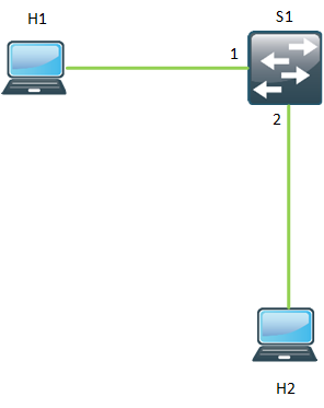
The first topology has two hosts H1 and H2 with IP addresses 10.0.0.10 and 10.0.0.20 respectively.

Host 1 and Host 2 are both connected to Switch 1 and has not communicated previously. H1 has the MAC address 0000.0000.0001 and H2 has the MAC address 0000.0000.0002. H1 wants to send data to H2, which steps are involved?
1. H1 knows the destination IP of H2 (10.0.0.20) and runs AND to determine that they are on the same subnet.
2. H1 checkts its ARP cache which is empty for 10.0.0.20.
3. H1 generates ARP message asking what the MAC address of H2 is. This frame has the destination MAC of ffff.ffff.ffff because it is a broadcast.
4. H1 sends the ARP frame out its Ethernet interface.
5. S1 receives the ARP frame, it has not previously heard from H1 so it adds 0000.0000.0001 to the MAC address table on port 1.
6. S1 checks the destination MAC of the ARP frame which is ffff.ffff.ffff, it floods the frame out all ports in the VLAN.
7. H2 receives the ARP frame and since the ARP is asking for the MAC of H2, it replies.
8. The ARP reply is unicast towards H1 and contains the MAC of H2.
9. S1 receives the ARP reply and adds H2 in the MAC address table, 0000.0000.0002 on port 2.
10. S1 forwards the frame to H1, it knows the MAC address from the previous ARP request.
11. H1 receives the ARP reply, learns the MAC of H2 and adds this to the ARP cache.
12. H1 now has all the information it needs. It generates a frame with source MAC of H1 and destination MAC of H2 and sends it out its port.
13. S1 receives the frame and forwards it out port 2.
14. H2 replies to the frame and sends it out its interface towards S1.
15. S1 receives the frame and forwards it out port 1.
16. The frame reaches H1, we have end to end communcation.
The thing to remember here is that unless the MAC is already known, ARP must be used to find the MAC of the other host. Understand how the switch learns MAC addresses by looking at incoming frames and that broadcast and unknown unicast frames will be flooded.
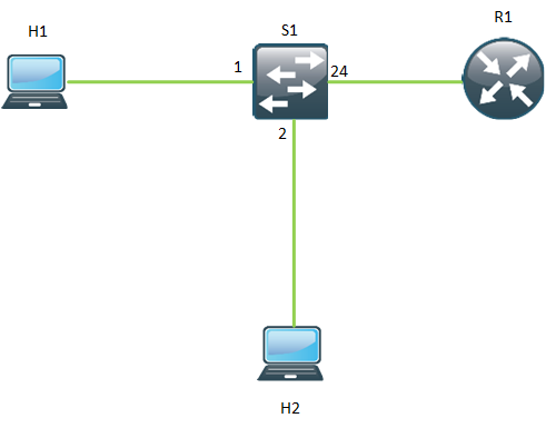
In the next example we add a router to the mix in a so called router on a stick setup. Host H1 still has IP 10.0.0.10 but H2 now has the IP address 20.0.0.20.

We now have hosts in different subnets which means that there is routing involved. This topology is router on a stick and the router will route packets between the subnets, it has an interface in both subnets, meaning that it is using subinterfaces. We start out a blank slate and go from there.
1. H1 wants to send data to H2. It does an AND to see if they are in the same subnet, which they are not.
2. H1 looks up its default gateway and checks if it has en entry in the ARP cache for the GW, which is doesnt.
3. H1 generates ARP request to ask for the MAC address of R1 and sends it out its interface.
4. S1 receives the ARP request with a destination MAC of ffff.ffff.ffff. It learns the MAC address of H1 on port 1 and adds it to the MAC address table. It floods the ARP request out all ports in the VLAN.
5. R1 receives the ARP request and sends an ARP reply with its MAC address.
6. S1 learns the MAC address of R1 on port 24 and adds it to the MAC address table.
7. S1 forwards the ARP reply to H1, the MAC of H1 is in the MAC address table.
8. H1 sends the IP packet out with a source MAC of H1 and a destination MAC of GW. Source IP is H1 and destination IP is H2.
9. S1 receives the frame and does lookup in the MAC address table. It forwards the frame out port 24.
10. R1 receives the frame and looks at the destination IP and then performs routing.
11. R1 does not know the MAC address of H2 so it generates an ARP request to find the MAC address of H2.
12. S1 receives the ARP request and floods it out all ports in the VLAN.
13. H2 receives the ARP request and then generates an ARP reply and sends it out its interface.
14. S1 receives the ARP reply and learns the MAC address of H2 on port 2 and adds it to the MAC address table.
15. S1 sends the ARP reply out port 24 to R1.
16. R1 now has the information to encapsulate the frame. It forwards the IP packet out its interface with source MAC of GW and destination MAC of H2. Source IP is H1 and destination IP is H2.
17. S1 receives the frame does a lookup in the MAC address table and then forwards it out port 2.
18. H2 receives the IP packet.
This should give you a basic understanding how the traffic flow goes on a LAN with a router involved. Normally things will already be in the ARP cache but for the sake of learning, assume that no traffic has been sent at all. Practice by drawing a topology on a piece of paper and then think of the traffic flow. You can also use tools as Packet Tracer to simulate traffic. Use Wireshark to see what really goes on the wire. What does an ARP request look like? What does an ARP reply look like? How can I check my ARP cache?
Good luck in your CCNA studies!
Hi Daniel!
How are you doing?
I would like to know if you have plans to continue with the blog posts (CCNA Workbook) that covers each item from the CCNA R&S blueprint?
Thank you in advance!
Regards,
Augusto
Hi Augusto,
I’m doing fine thanks. How about you? I would like to continue the CCNA blog posts but I think I understimated the time needed for each post if I want to keep the quality that I always to try to keep in my posts. I’m also very busy preparing for the CCDE right now. Sorry for any inconvenience.
Best regards,
Daniel
I’m fine , thanks! Thank you for the response. Good luck on your CCDE practical exam!
Regards,
Augusto
This is amazing