Maximum Segment Size (MSS) and MSS clamping are concepts that can be confusing. How do they relate to the MTU (Maximum Transmission Unit)? Before we setup a lab to demonstrate these concepts, let’s give some background. Note that this entire post assumes a maximum frame size of 1518 bytes, the original Ethernet definition, and does not cover jumbo frames.
Ethernet frame
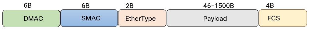
Almost all interfaces today are Ethernet. The original 802.3 standard from 1985 defined the minimum size- and maximum size frame as the following:
- minFrameSize – 64 octets.
- maxFrameSize – 1518 octets.
With a maximum frame size of 1518 octets (bytes), that leaves 1500 bytes of payload as the Ethernet frame adds 18 bytes, 14 bytes of header and 4 bytes of trailer. The Ethernet frame is shown below:
IP header
An IPv4 IP header adds at least 20 bytes to the frame. The IPv4 header is shown below:
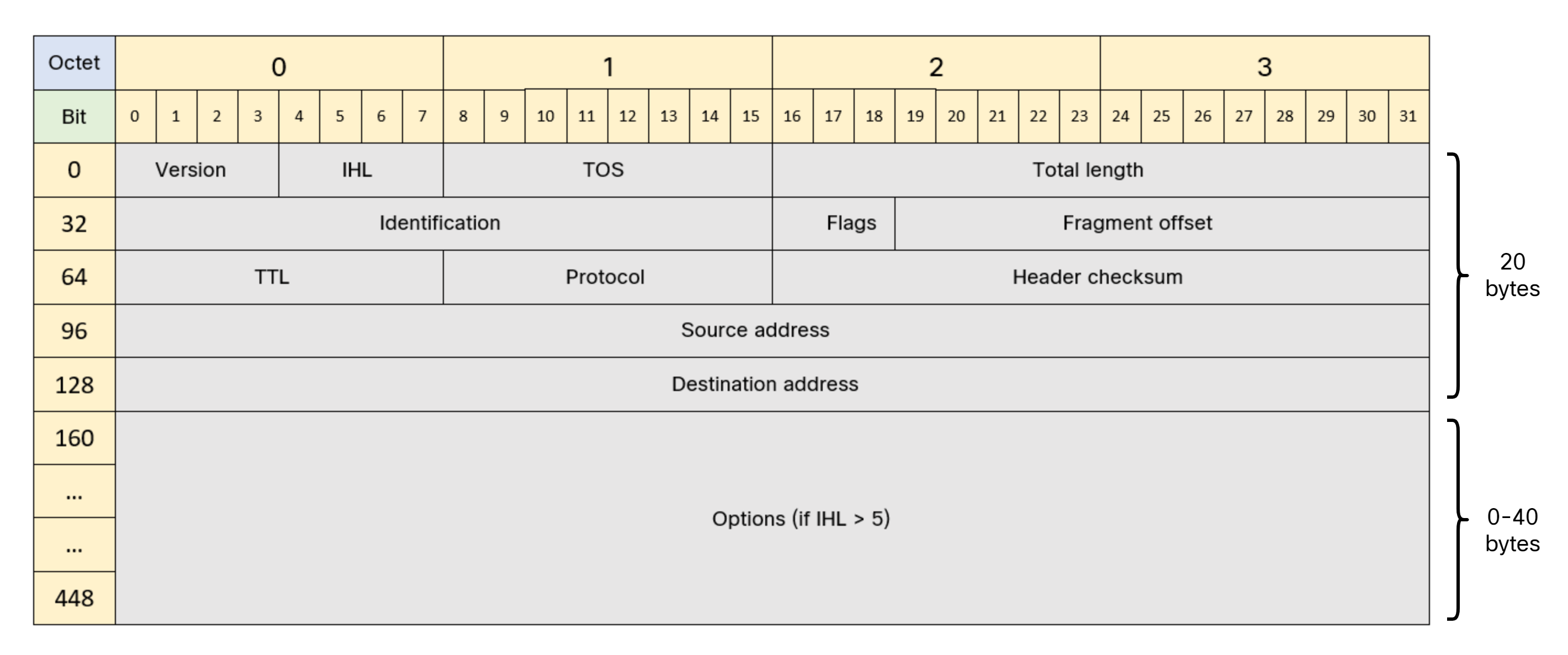
Note that more than 20 bytes can be used if the header has IP options. With no options in the IP header, there’s 1480 bytes remaining for the L4 protocol such as UDP or TCP.
TCP header
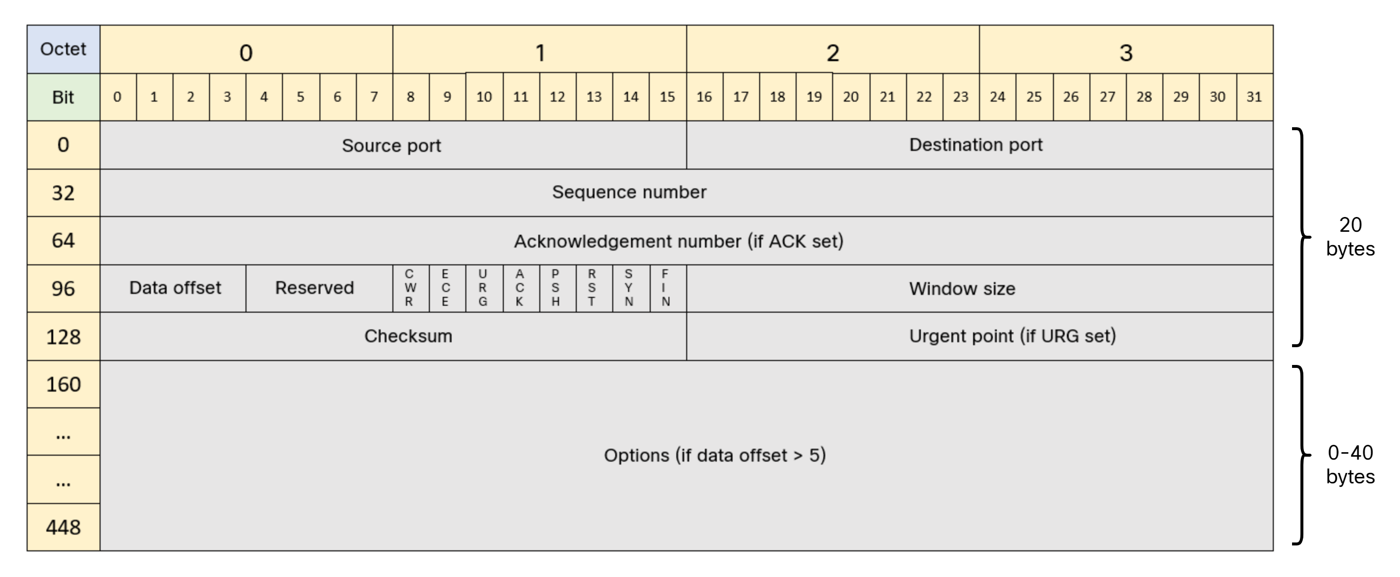
TCP also adds a minimum of 20 bytes, meaning that the maximum payload that TCP can carry, the maximum segment size, is 1460 bytes. The TCP header is shown below:
Let’s do the numbers:
- TCP payload – 1460 bytes.
- TCP header – 20 bytes.
- IP header – 20 bytes.
- Ethernet frame – 18 bytes.
- Total – 1518 bytes.
This is shown in the picture below:
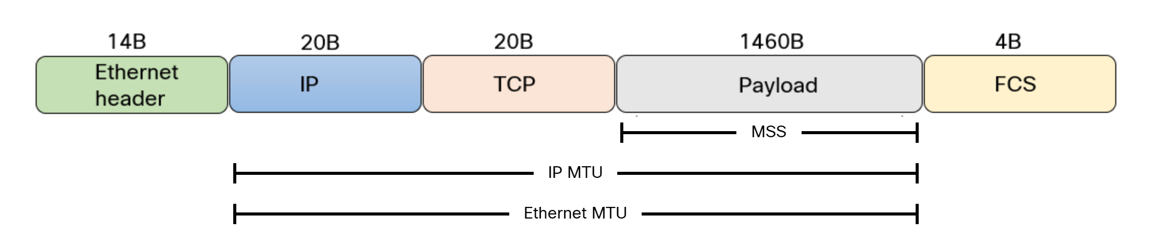
Note that the IPv4 header can be larger than 20 bytes when using options, and the same for TCP.
TCP MSS
We now know that hosts will not generate larger packets than 1500 bytes and that the MSS is most commonly 1460 bytes. Now let’s learn some more about MSS:
- MSS is not negotiated.
- MSS is a TCP option set in SYN segments.
- MSS is derived from the IP MTU.
- It is used to indicate how large segments the host is willing to receive.
- MSS is not bidirectional.
- MSS can be different in each direction.
- MSS can be modified by an intermediate device.
It’s important to understand that the MSS is only set in SYN segments. When are SYN segments sent? When a TCP session is established using the three-way handshake:
- SYN.
- SYN, ACK.
- ACK.
The TCP three-way handshake is displayed below:
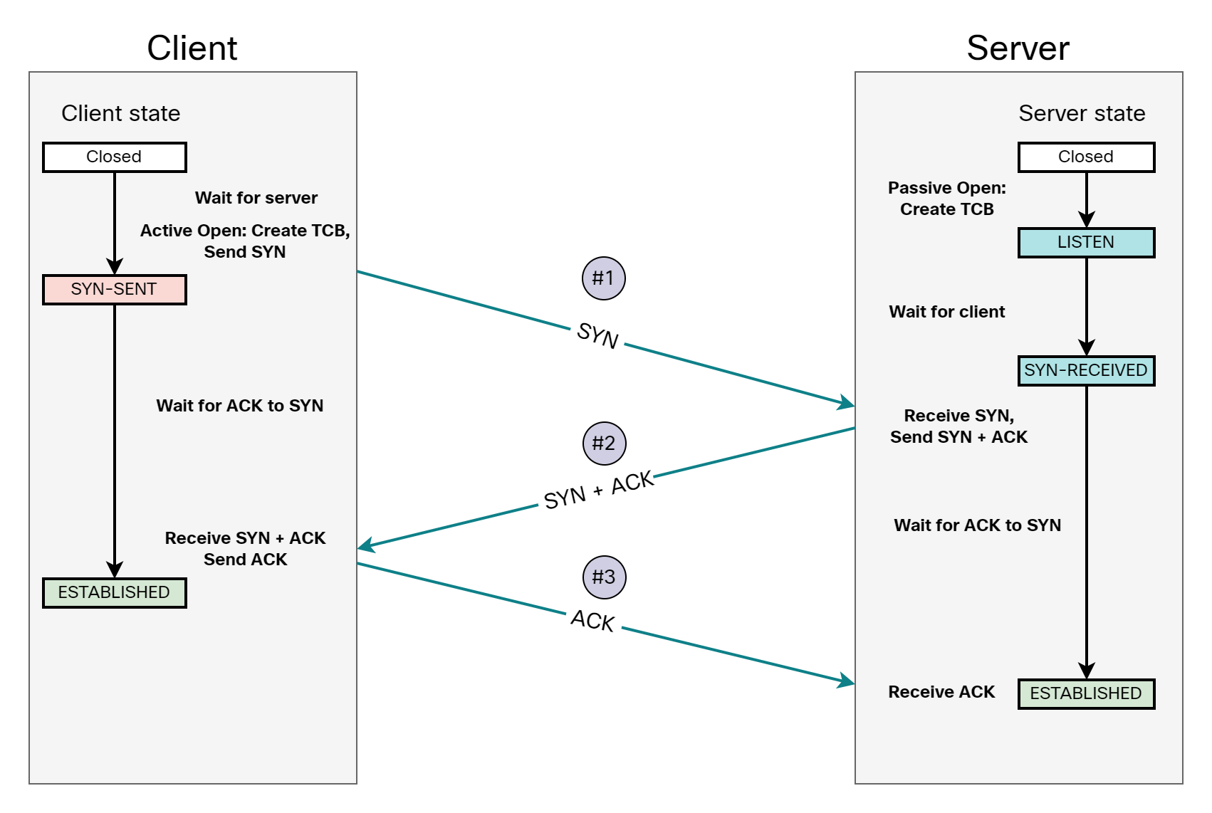
Once a MSS has been set for a session, that value is used until the session is closed. There’s no way of modifying MSS once the session is established without terminating it and establishing a new one.
Lab
With that understanding of MSS, let’s proceed to setup a simple lab to demonstrate it in practice.
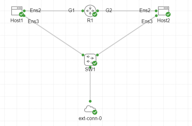
There’s two Ubuntu hosts, named Host1 and Host2. There’s a router, named R1, which I intend to use to modify MSS. There’s also an unmanaged switch connected to an external connector doing NAT. I’m using the external connector to provide internet access to the hosts to be able to download software such as iPerf.
Verifying MTU
Let’s first verify the MTU of the interface of Host1:
cisco@Host1:~$ ip addr | grep ens2
2: ens2: <BROADCAST,MULTICAST,UP,LOWER_UP> mtu 1500 qdisc fq_codel state UP group default qlen 1000
    inet 10.0.0.10/24 scope global ens2
The MTU of the network interface ens2 is 1500 bytes as expected.
Path MTU discovery
Let’s also verify the MTU of the path using tracepath command. This will perform Path MTU Discovery (PMTUD):
cisco@Host1:~$ tracepath 10.0.1.10
 1?: [LOCALHOST]                      pmtu 1500
 1:  10.0.0.1                                              0.972ms
 1:  10.0.0.1                                              0.823ms
 2:  10.0.1.10                                             1.373ms reached
     Resume: pmtu 1500 hops 2 back 2
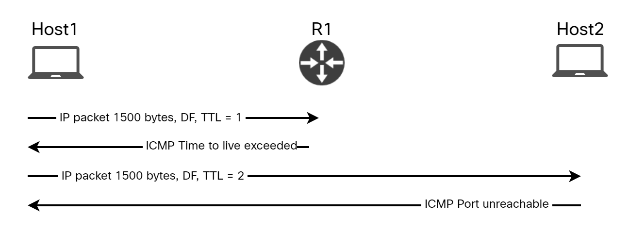
The path MTU is 1500 bytes. Tracepath discovers the PMTU by sending UDP packets of maximum size, 1472 bytes of payload. Because the UDP header is only 8 bytes, it can have a payload of 1472 bytes, as opposed to 1460 for TCP. Below is the first packet sent by Host1:
Frame 4: 1514 bytes on wire (12112 bits), 1514 bytes captured (12112 bits)
Ethernet II, Src: 52:54:00:11:fc:84, Dst: 52:54:00:1b:58:2f
Internet Protocol Version 4, Src: 10.0.0.10, Dst: 10.0.1.10
    0100 .... = Version: 4
    .... 0101 = Header Length: 20 bytes (5)
    Differentiated Services Field: 0x00 (DSCP: CS0, ECN: Not-ECT)
    Total Length: 1500
    Identification: 0x0000 (0)
    010. .... = Flags: 0x2, Don't fragment
    ...0 0000 0000 0000 = Fragment Offset: 0
    Time to Live: 1
    Protocol: UDP (17)
    Header Checksum: 0x5efe [validation disabled]
    [Header checksum status: Unverified]
    Source Address: 10.0.0.10
    Destination Address: 10.0.1.10
User Datagram Protocol, Src Port: 54268, Dst Port: 44445
Data (1472 bytes)
Note the use of Don’t Fragment in the IP header. If the router were to fragment the packet, we wouldn’t find out the path MTU.
The router receives the packet on Gi1 and responds as the TTL has expired:
Frame 5: 70 bytes on wire (560 bits), 70 bytes captured (560 bits)
Ethernet II, Src: 52:54:00:1b:58:2f, Dst: 52:54:00:11:fc:84
Internet Protocol Version 4, Src: 10.0.0.1, Dst: 10.0.0.10
    0100 .... = Version: 4
    .... 0101 = Header Length: 20 bytes (5)
    Differentiated Services Field: 0x00 (DSCP: CS0, ECN: Not-ECT)
    Total Length: 56
    Identification: 0x0000 (0)
    000. .... = Flags: 0x0
    ...0 0000 0000 0000 = Fragment Offset: 0
    Time to Live: 255
    Protocol: ICMP (1)
    Header Checksum: 0xa7ba [validation disabled]
    [Header checksum status: Unverified]
    Source Address: 10.0.0.1
    Destination Address: 10.0.0.10
Internet Control Message Protocol
    Type: 11 (Time-to-live exceeded)
    Code: 0 (Time to live exceeded in transit)
    Checksum: 0x4d81 [correct]
    [Checksum Status: Good]
    Unused: 00000000
    Internet Protocol Version 4, Src: 10.0.0.10, Dst: 10.0.1.10
        0100 .... = Version: 4
        .... 0101 = Header Length: 20 bytes (5)
        Differentiated Services Field: 0x00 (DSCP: CS0, ECN: Not-ECT)
        Total Length: 1500
        Identification: 0x0000 (0)
        010. .... = Flags: 0x2, Don't fragment
        ...0 0000 0000 0000 = Fragment Offset: 0
        Time to Live: 1
        Protocol: UDP (17)
        Header Checksum: 0x5efe [validation disabled]
        [Header checksum status: Unverified]
        Source Address: 10.0.0.10
        Destination Address: 10.0.1.10
    User Datagram Protocol, Src Port: 54268, Dst Port: 44445
Next, the packet from Host1 is sent with a TTL of 2:
Frame 6: 1514 bytes on wire (12112 bits), 1514 bytes captured (12112 bits)
Ethernet II, Src: 52:54:00:11:fc:84, Dst: 52:54:00:1b:58:2f
Internet Protocol Version 4, Src: 10.0.0.10, Dst: 10.0.1.10
    0100 .... = Version: 4
    .... 0101 = Header Length: 20 bytes (5)
    Differentiated Services Field: 0x00 (DSCP: CS0, ECN: Not-ECT)
    Total Length: 1500
    Identification: 0x0000 (0)
    010. .... = Flags: 0x2, Don't fragment
    ...0 0000 0000 0000 = Fragment Offset: 0
    Time to Live: 2
    Protocol: UDP (17)
    Header Checksum: 0x5dfe [validation disabled]
    [Header checksum status: Unverified]
    Source Address: 10.0.0.10
    Destination Address: 10.0.1.10
User Datagram Protocol, Src Port: 54268, Dst Port: 44446
Data (1472 bytes)
Host2 then responds with Port unreachable:
Frame 7: 590 bytes on wire (4720 bits), 590 bytes captured (4720 bits)
Ethernet II, Src: 52:54:00:1b:58:2f, Dst: 52:54:00:11:fc:84
Internet Protocol Version 4, Src: 10.0.1.10, Dst: 10.0.0.10
    0100 .... = Version: 4
    .... 0101 = Header Length: 20 bytes (5)
    Differentiated Services Field: 0xc0 (DSCP: CS6, ECN: Not-ECT)
    Total Length: 576
    Identification: 0x2f73 (12147)
    000. .... = Flags: 0x0
    ...0 0000 0000 0000 = Fragment Offset: 0
    Time to Live: 63
    Protocol: ICMP (1)
    Header Checksum: 0x3477 [validation disabled]
    [Header checksum status: Unverified]
    Source Address: 10.0.1.10
    Destination Address: 10.0.0.10
Internet Control Message Protocol
    Type: 3 (Destination unreachable)
    Code: 3 (Port unreachable)
    Checksum: 0x17ea [correct]
    [Checksum Status: Good]
    Unused: 00000000
    Internet Protocol Version 4, Src: 10.0.0.10, Dst: 10.0.1.10
        0100 .... = Version: 4
        .... 0101 = Header Length: 20 bytes (5)
        Differentiated Services Field: 0x00 (DSCP: CS0, ECN: Not-ECT)
        Total Length: 1500
        Identification: 0x0000 (0)
        010. .... = Flags: 0x2, Don't fragment
        ...0 0000 0000 0000 = Fragment Offset: 0
        Time to Live: 1
        Protocol: UDP (17)
        Header Checksum: 0x5efe [validation disabled]
        [Header checksum status: Unverified]
        Source Address: 10.0.0.10
        Destination Address: 10.0.1.10
    User Datagram Protocol, Src Port: 54268, Dst Port: 44446
Data (520 bytes)
The process of PMTUD is shown below:
This is all a little too convenient as the MTU is the same end to end. Let’s modify the IP MTU on R1’s interface towards Host1 and try again:
R1(config)#int gi1
R1(config-if)#ip mtu 1400
cisco@Host1:~$ tracepath 10.0.1.10
 1?: [LOCALHOST]                      pmtu 1500
 1:  10.0.0.1                                              1.086ms
 1:  10.0.0.1                                              0.844ms
 2:  10.0.1.10                                             1.565ms reached
     Resume: pmtu 1500 hops 2 back 2
What’s this? Why do we have a PMTU of 1500? It caught me by surprise at first until I realized that MTU is Maximum TRANSMISSION Unit. There’s also something called Maximum Receive Unit (MRU). Changing the IP MTU on GigabitEthernet1 means it wont transmit packets larger than 1400 bytes, but it can still receive them! Here’s what happened:
As you can see, R1 didn’t have to transmit anything larger than 590 bytes towards Host1, which is well below the 1400 bytes of IP MTU.
After modifying the IP MTU on the interface towards Host2, we see the intended effect on PMTU:
cisco@Host1:~$ tracepath 10.0.1.10
 1?: [LOCALHOST]                      pmtu 1500
 1:  10.0.0.1                                              2.920ms
 1:  10.0.0.1                                              0.940ms
 2:  10.0.0.1                                              0.856ms pmtu 1400
 2:  10.0.1.10                                             1.383ms reached
     Resume: pmtu 1400 hops 2 back 2
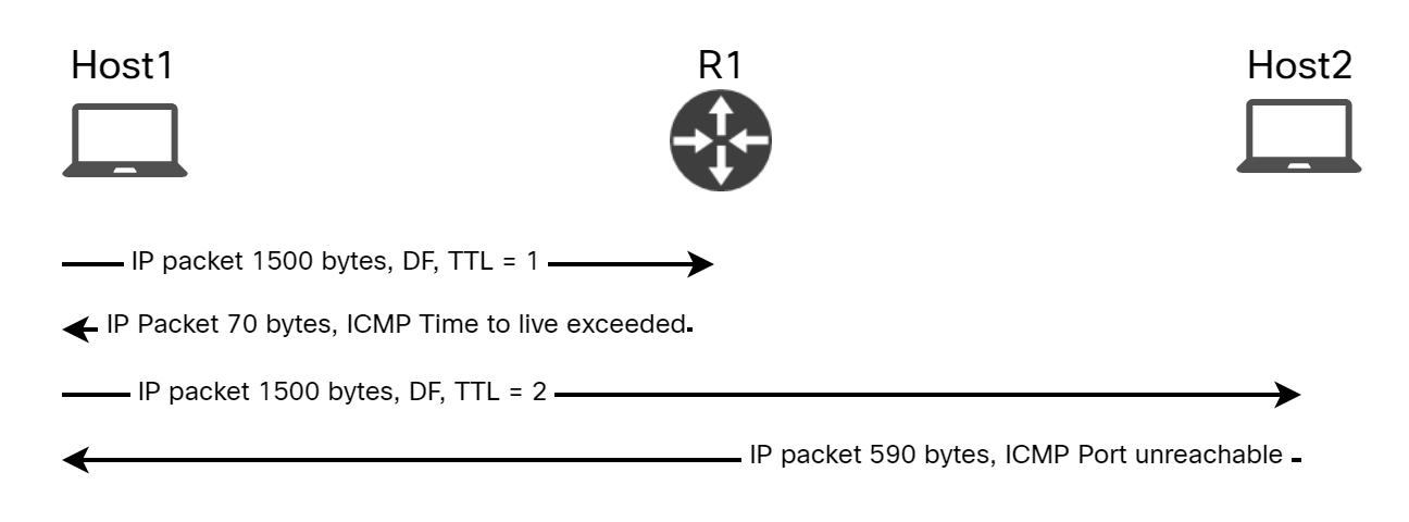
The diagram below shows the packets involved:
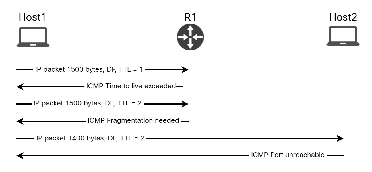
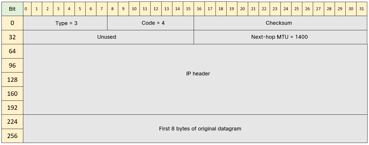
How does Host1 know how much to lower the packet size by? This information is sent from R1 in the ICMP message:
Frame 16: 70 bytes on wire (560 bits), 70 bytes captured (560 bits)
Ethernet II, Src: 52:54:00:1b:58:2f, Dst: 52:54:00:11:fc:84
Internet Protocol Version 4, Src: 10.0.0.1, Dst: 10.0.0.10
    0100 .... = Version: 4
    .... 0101 = Header Length: 20 bytes (5)
    Differentiated Services Field: 0x00 (DSCP: CS0, ECN: Not-ECT)
    Total Length: 56
    Identification: 0x0000 (0)
    000. .... = Flags: 0x0
    ...0 0000 0000 0000 = Fragment Offset: 0
    Time to Live: 255
    Protocol: ICMP (1)
    Header Checksum: 0xa7ba [validation disabled]
    [Header checksum status: Unverified]
    Source Address: 10.0.0.1
    Destination Address: 10.0.0.10
    [Stream index: 2]
Internet Control Message Protocol
    Type: 3 (Destination unreachable)
    Code: 4 (Fragmentation needed)
    Checksum: 0x6cbb [correct]
    [Checksum Status: Good]
    Unused: 0000
    MTU of next hop: 1400
    Internet Protocol Version 4, Src: 10.0.0.10, Dst: 10.0.1.10
    User Datagram Protocol, Src Port: 59335, Dst Port: 44446
Notice that it says MTU of next hop: 1400. The ICMP Fragmentation needed message is shown below:
TCP MSS
With a solid understanding of the different headers, their size, and how PMTUD is performed, let’s move on to seeing MSS and MSS clamping in practice. I have restored the IP MTU of the interfaces on the router. We will be using iPerf to setup TCP sessions that we can inspect.
Before starting iPerf, let’s learn a bit about the socket statistics command. It can be used to show what sockets are in use by what process. Let’s give it a try:
cisco@Host1:~$ ss -taoipnm
State     Recv-Q    Send-Q       Local Address:Port        Peer Address:Port    Process
LISTEN    0         4096         127.0.0.53%lo:53               0.0.0.0:*
         skmem:(r0,rb131072,t0,tb16384,f0,w0,o0,bl0,d0) cubic cwnd:10
LISTEN    0         128                0.0.0.0:22               0.0.0.0:*
         skmem:(r0,rb131072,t0,tb16384,f0,w0,o0,bl0,d0) cubic cwnd:10
LISTEN    0         128                   [::]:22                  [::]:*
         skmem:(r0,rb131072,t0,tb16384,f0,w0,o0,bl0,d0) cubic cwnd:10
This commands gives us information about:
- t – TCP sockets only.
- a – All sockets, including those that are listening.
- o – Options, shows timer information.
- i – Info, internal TCP information.
- p – Processes, what process is using what socket.
- n – Numeric, don’t resolve service names.
- m – Memory, show how much memory the socket is using.
Currently, the host is only listening on port 22 (SSH) for both IPv4 (0.0.0.0) and IPv6 (::).
I’ll now start iPerf3 server on this host running in daemon mode:
cisco@Host1:~$ iperf3 -sD
If we run the ss command again, we should now see the iPerf process:
cisco@Host1:~$ ss -taoipnm
State     Recv-Q    Send-Q       Local Address:Port        Peer Address:Port    Process
LISTEN    0         4096                     *:5201                   *:*        users:(("iperf3",pid=45227,fd=3))
         skmem:(r0,rb131072,t0,tb16384,f0,w0,o0,bl0,d0) cubic cwnd:10
We can see that the Transmission Control Block (TCB) is in listen state. I’ll now initiate the iPerf test from Host2:
cisco@Host2:~$ iperf3 -c 10.0.0.10 -t 20
Connecting to host 10.0.0.10, port 5201
[  5] local 10.0.1.10 port 58170 connected to 10.0.0.10 port 5201
[ ID] Interval           Transfer     Bitrate         Retr  Cwnd
[  5]   0.00-1.00   sec  4.79 MBytes  40.2 Mbits/sec    0   89.1 KBytes
[  5]   1.00-2.00   sec  2.42 MBytes  20.3 Mbits/sec    0    107 KBytes
[  5]   2.00-3.00   sec  2.24 MBytes  18.8 Mbits/sec    0    123 KBytes
[  5]   3.00-4.00   sec  2.24 MBytes  18.8 Mbits/sec    0    136 KBytes
[  5]   4.00-5.00   sec  2.49 MBytes  20.9 Mbits/sec    0    148 KBytes
[  5]   5.00-6.00   sec  2.17 MBytes  18.2 Mbits/sec    0    160 KBytes
[  5]   6.00-7.00   sec  2.17 MBytes  18.2 Mbits/sec    0    170 KBytes
[  5]   7.00-8.00   sec  2.24 MBytes  18.8 Mbits/sec    0    180 KBytes
[  5]   8.00-9.00   sec  2.24 MBytes  18.8 Mbits/sec    0    189 KBytes
[  5]   9.00-10.00  sec  2.42 MBytes  20.3 Mbits/sec    0    222 KBytes
[  5]  10.00-11.00  sec  2.55 MBytes  21.4 Mbits/sec    0    297 KBytes
[  5]  11.00-12.00  sec  2.73 MBytes  22.9 Mbits/sec    0    396 KBytes
[  5]  12.00-13.00  sec  2.67 MBytes  22.4 Mbits/sec    0    519 KBytes
[  5]  13.00-14.00  sec  2.24 MBytes  18.8 Mbits/sec   23    461 KBytes
[  5]  14.00-15.00  sec  2.49 MBytes  20.9 Mbits/sec    7    486 KBytes
[  5]  15.00-16.00  sec  2.49 MBytes  20.9 Mbits/sec    0    543 KBytes
[  5]  16.00-17.00  sec  2.49 MBytes  20.9 Mbits/sec    0    585 KBytes
[  5]  17.00-18.00  sec  1.24 MBytes  10.4 Mbits/sec    6    420 KBytes
[  5]  18.00-19.00  sec  3.73 MBytes  31.3 Mbits/sec    0    455 KBytes
[  5]  19.00-20.00  sec  1.24 MBytes  10.4 Mbits/sec    0    484 KBytes
- - - - - - - - - - - - - - - - - - - - - - - - -
[ ID] Interval           Transfer     Bitrate         Retr
[  5]   0.00-20.00  sec  49.3 MBytes  20.7 Mbits/sec   36             sender
[  5]   0.00-20.25  sec  47.3 MBytes  19.6 Mbits/sec                  receiver

iperf Done.
Let’s check the sockets on Host1 and Host2:
cisco@Host1:~$ ss -taoipnm
State   Recv-Q  Send-Q         Local Address:Port           Peer Address:Port   Process
ESTAB   1448    0         [::ffff:10.0.0.10]:5201     [::ffff:10.0.1.10]:58170   users:(("iperf3",pid=45227,fd=5))
         skmem:(r2304,rb6291456,t0,tb87040,f63232,w0,o0,bl0,d0) ts sack cubic wscale:7,7 rto:204 rtt:1.043/0.521 ato:40 mss:1448 pmtu:1500 rcvmss:1448 advmss:1448 cwnd:10 bytes_received:15322773 segs_out:4818 segs_in:10585 data_segs_in:10583 send 111064238bps lastsnd:5576 lastack:5444 pacing_rate 222128472bps delivered:1 app_limited rcv_rtt:65.802 rcv_space:159280 rcv_ssthresh:3144576 minrtt:1.043
ESTAB   0       0         [::ffff:10.0.0.10]:5201     [::ffff:10.0.1.10]:58154   users:(("iperf3",pid=45227,fd=4))
         skmem:(r0,rb131072,t0,tb87040,f0,w0,o0,bl0,d0) ts sack cubic wscale:7,7 rto:208 rtt:6.011/9.613 ato:40 mss:1448 pmtu:1500 rcvmss:536 advmss:1448 cwnd:10 bytes_sent:4 bytes_acked:4 bytes_received:141 segs_out:6 segs_in:8 data_segs_out:3 data_segs_in:3 send 19271336bps lastsnd:5536 lastrcv:5580 lastack:5536 pacing_rate 38541064bps delivery_rate 9282048bps delivered:4 app_limited busy:48ms rcv_space:14600 rcv_ssthresh:64076 minrtt:1.248
cisco@Host2:~$ ss -taoipnm
State     Recv-Q    Send-Q       Local Address:Port        Peer Address:Port    Process
ESTAB     0         490872           10.0.1.10:58170          10.0.0.10:5201     users:(("iperf3",pid=44873,fd=5)) timer:(on,124ms,0)
         skmem:(r0,rb131072,t0,tb792064,f231816,w558712,o0,bl0,d0) ts sack cubic wscale:7,7 rto:260 rtt:56.842/0.771 mss:1448 pmtu:1500 rcvmss:536 advmss:1448 cwnd:91 ssthresh:39 bytes_sent:10596501 bytes_acked:10464734 segs_out:7321 segs_in:3211 data_segs_out:7319 send 18545160bps lastrcv:3504 pacing_rate 22253896bps delivery_rate 18856552bps delivered:7229 busy:3464ms unacked:91 reordering:12 reord_seen:3 rcv_space:14480 rcv_ssthresh:64088 notsent:359104 minrtt:0.924
ESTAB     0         0                10.0.1.10:58154          10.0.0.10:5201     users:(("iperf3",pid=44873,fd=4))
         skmem:(r0,rb131072,t0,tb87040,f0,w0,o0,bl0,d0) ts sack cubic wscale:7,7 rto:208 rtt:6.555/10.271 ato:40 mss:1448 pmtu:1500 rcvmss:536 advmss:1448 cwnd:10 bytes_sent:141 bytes_acked:142 bytes_received:4 segs_out:8 segs_in:7 data_segs_out:3 data_segs_in:3 send 17672006bps lastsnd:3508 lastrcv:3464 lastack:3508 pacing_rate 35344008bps delivery_rate 10099384bps delivered:4 busy:48ms rcv_space:14480 rcv_ssthresh:64088 minrtt:1.141
There’s actually two streams. What’s also interesting is that the MSS is set to 1448 bytes, not 1460. Why is that? Let’s look at the packets! Initially, Host2 sends the SYN:
Frame 1: 74 bytes on wire (592 bits), 74 bytes captured (592 bits)
Ethernet II, Src: 52:54:00:1b:58:2f, Dst: 52:54:00:11:fc:84
Internet Protocol Version 4, Src: 10.0.1.10, Dst: 10.0.0.10
Transmission Control Protocol, Src Port: 58154, Dst Port: 5201, Seq: 0, Len: 0
    Source Port: 58154
    Destination Port: 5201
    [Stream index: 0]
    [Stream Packet Number: 1]
    [Conversation completeness: Incomplete, DATA (15)]
    [TCP Segment Len: 0]
    Sequence Number: 0    (relative sequence number)
    Sequence Number (raw): 389463509
    [Next Sequence Number: 1    (relative sequence number)]
    Acknowledgment Number: 0
    Acknowledgment number (raw): 0
    1010 .... = Header Length: 40 bytes (10)
    Flags: 0x002 (SYN)
    Window: 64240
    [Calculated window size: 64240]
    Checksum: 0x361a [unverified]
    [Checksum Status: Unverified]
    Urgent Pointer: 0
    Options: (20 bytes), Maximum segment size, SACK permitted, Timestamps, No-Operation (NOP), Window scale
        TCP Option - Maximum segment size: 1460 bytes
        TCP Option - SACK permitted
        TCP Option - Timestamps: TSval 2736689723, TSecr 0
        TCP Option - No-Operation (NOP)
        TCP Option - Window scale: 7 (multiply by 128)
    [Timestamps]
The MSS is set to 1460 as expected. We notice that there’s 20 bytes of TCP options that are set, making the TCP header 40 bytes in total. The options are:
- Maximum segment size – 4 bytes.
- Selective acknowledgement permitted – 2 bytes.
- Timestamps – 10 bytes.
- No operation (to align options field on 32-bit boundaries) – 1 byte.
- Window scale – 3 bytes.
Notice that without NOP, there would be 19 bytes of options (4+2+10+3), which would not align on a 32-bit boundary. Therefore, NOP is adding an additional byte.
Host1 then sends the SYN + ACK:
Frame 2: 74 bytes on wire (592 bits), 74 bytes captured (592 bits)
Ethernet II, Src: 52:54:00:11:fc:84, Dst: 52:54:00:1b:58:2f
Internet Protocol Version 4, Src: 10.0.0.10, Dst: 10.0.1.10
Transmission Control Protocol, Src Port: 5201, Dst Port: 58154, Seq: 0, Ack: 1, Len: 0
    Source Port: 5201
    Destination Port: 58154
    [Stream index: 0]
    [Stream Packet Number: 2]
    [Conversation completeness: Incomplete, DATA (15)]
    [TCP Segment Len: 0]
    Sequence Number: 0    (relative sequence number)
    Sequence Number (raw): 1614256318
    [Next Sequence Number: 1    (relative sequence number)]
    Acknowledgment Number: 1    (relative ack number)
    Acknowledgment number (raw): 389463510
    1010 .... = Header Length: 40 bytes (10)
    Flags: 0x012 (SYN, ACK)
    Window: 65160
    [Calculated window size: 65160]
    Checksum: 0x13b0 [unverified]
    [Checksum Status: Unverified]
    Urgent Pointer: 0
    Options: (20 bytes), Maximum segment size, SACK permitted, Timestamps, No-Operation (NOP), Window scale
        TCP Option - Maximum segment size: 1460 bytes
        TCP Option - SACK permitted
        TCP Option - Timestamps: TSval 1491324135, TSecr 2736689723
        TCP Option - No-Operation (NOP)
        TCP Option - Window scale: 7 (multiply by 128)
    [Timestamps]
    [SEQ/ACK analysis]
Host2 sends the ACK:
Frame 3: 66 bytes on wire (528 bits), 66 bytes captured (528 bits)
Ethernet II, Src: 52:54:00:1b:58:2f, Dst: 52:54:00:11:fc:84
Internet Protocol Version 4, Src: 10.0.1.10, Dst: 10.0.0.10
Transmission Control Protocol, Src Port: 58154, Dst Port: 5201, Seq: 1, Ack: 1, Len: 0
    Source Port: 58154
    Destination Port: 5201
    [Stream index: 0]
    [Stream Packet Number: 3]
    [Conversation completeness: Incomplete, DATA (15)]
    [TCP Segment Len: 0]
    Sequence Number: 1    (relative sequence number)
    Sequence Number (raw): 389463510
    [Next Sequence Number: 1    (relative sequence number)]
    Acknowledgment Number: 1    (relative ack number)
    Acknowledgment number (raw): 1614256319
    1000 .... = Header Length: 32 bytes (8)
    Flags: 0x010 (ACK)
    Window: 502
    [Calculated window size: 64256]
    [Window size scaling factor: 128]
    Checksum: 0x3f0d [unverified]
    [Checksum Status: Unverified]
    Urgent Pointer: 0
    Options: (12 bytes), No-Operation (NOP), No-Operation (NOP), Timestamps
        TCP Option - No-Operation (NOP)
        TCP Option - No-Operation (NOP)
        TCP Option - Timestamps: TSval 2736689725, TSecr 1491324135
    [Timestamps]
    [SEQ/ACK analysis]
Because this packet has no SYN, there is no MSS in it. Also note that the TCP timestamp is 10 bytes, which means two NOP are needed, adding an additional byte each, to make the TCP options 12 bytes in total, and hence aligning on 32-bit boundary. All the frames sent by iPerf are 1514 bytes in total:
- Ethernet – 14 bytes.
- IP – 1500 bytes.
- TCP – 1480 bytes.
- TCP payload – 1448 bytes.
- TCP header – 32 bytes, whereof:
- TCP options – 12 bytes.
While the MSS sent by Host1 was 1460, when using 12 bytes for TCP options, that leaves 1448 bytes for the payload.
Now that we have an understanding of how MSS works. Let’s make it more interesting by using different IP MTUs on the hosts. We’ll keep Host2 at 1500 bytes, but change Host1 to 1400 bytes. What I’m expecting is this:
- Host2 will have a MSS of 1460 bytes in its SYN.
- Host1 will have a MSS of 1360 bytes in its SYN + ACK.
- Host2 will use a MSS of 1348 (1360-12) bytes towards Host1.
- Host1 will use a MSS of 1348 (1360-12) bytes towards Host2.
Let’s see if our logic checks out. I’ll start by modifying the MTU on Host1:
cisco@Host1:~$ sudo ip link set dev ens2 mtu 1400
cisco@Host1:~$ ip addr | grep ens2
2: ens2: <BROADCAST,MULTICAST,UP,LOWER_UP> mtu 1400 qdisc fq_codel state UP group default qlen 1000
    inet 10.0.0.10/24 scope global ens2
I’ll initiate iPerf on Host2 and then check the sockets on the two hosts:
cisco@Host2:~$ iperf3 -c 10.0.0.10 -t 10
Connecting to host 10.0.0.10, port 5201
[  5] local 10.0.1.10 port 37006 connected to 10.0.0.10 port 5201
[ ID] Interval           Transfer     Bitrate         Retr  Cwnd
[  5]   0.00-1.00   sec  5.10 MBytes  42.8 Mbits/sec    0    254 KBytes
[  5]   1.00-2.00   sec  2.59 MBytes  21.7 Mbits/sec    0    369 KBytes
[  5]   2.00-3.00   sec  2.53 MBytes  21.2 Mbits/sec    0    482 KBytes
[  5]   3.00-4.00   sec  1.79 MBytes  15.0 Mbits/sec   11    477 KBytes
[  5]   4.00-5.00   sec  2.72 MBytes  22.8 Mbits/sec   10    442 KBytes
[  5]   5.00-6.00   sec  2.04 MBytes  17.1 Mbits/sec    0    495 KBytes
[  5]   6.00-7.00   sec  2.72 MBytes  22.8 Mbits/sec    0    534 KBytes
[  5]   7.00-8.00   sec  2.04 MBytes  17.1 Mbits/sec    2    544 KBytes
[  5]   8.00-9.00   sec  2.22 MBytes  18.6 Mbits/sec    3    411 KBytes
[  5]   9.00-10.00  sec  2.04 MBytes  17.1 Mbits/sec    0    441 KBytes
- - - - - - - - - - - - - - - - - - - - - - - - -
[ ID] Interval           Transfer     Bitrate         Retr
[  5]   0.00-10.00  sec  25.8 MBytes  21.6 Mbits/sec   26             sender
[  5]   0.00-10.23  sec  24.8 MBytes  20.4 Mbits/sec                  receiver

iperf Done.
cisco@Host2:~$ ss -taoipnm
State    Recv-Q    Send-Q        Local Address:Port        Peer Address:Port    Process
ESTAB    0         1005608           10.0.1.10:37006          10.0.0.10:5201     users:(("iperf3",pid=45482,fd=5)) timer:(on,208ms,0)
         skmem:(r0,rb131072,t0,tb1847808,f497624,w1271848,o0,bl0,d0) ts sack cubic wscale:7,7 rto:424 rtt:220.211/0.771 mss:1348 pmtu:1500 rcvmss:536 advmss:1448 cwnd:401 ssthresh:20 bytes_sent:10833913 bytes_acked:10294714 segs_out:8040 segs_in:3154 data_segs_out:8038 send 19637457bps lastrcv:3444 pacing_rate 23564944bps delivery_rate 18632792bps delivered:7639 busy:3408ms unacked:400 rcv_space:14480 rcv_ssthresh:64088 notsent:466408 minrtt:0.935
ESTAB    0         0                 10.0.1.10:37000          10.0.0.10:5201     users:(("iperf3",pid=45482,fd=4))
         skmem:(r0,rb131072,t0,tb46080,f0,w0,o0,bl0,d0) ts sack cubic wscale:7,7 rto:208 rtt:6.087/9.565 ato:40 mss:1348 pmtu:1500 rcvmss:536 advmss:1448 cwnd:10 bytes_sent:141 bytes_acked:142 bytes_received:4 segs_out:8 segs_in:7 data_segs_out:3 data_segs_in:3 send 17716445bps lastsnd:3448 lastrcv:3404 lastack:3448 pacing_rate 35429976bps delivery_rate 8641024bps delivered:4 busy:44ms rcv_space:14480 rcv_ssthresh:64088 minrtt:1.166
Notice that the MSS (Effective Send MSS) is set to 1348. Let’s also check Host1:
cisco@Host1:~$ ss -taoipnm
State   Recv-Q  Send-Q         Local Address:Port           Peer Address:Port   Process
ESTAB   0       0         [::ffff:10.0.0.10]:5201     [::ffff:10.0.1.10]:37000   users:(("iperf3",pid=45227,fd=4))
         skmem:(r0,rb131072,t0,tb87040,f0,w0,o0,bl0,d0) ts sack cubic wscale:7,7 rto:208 rtt:5.779/9.336 ato:40 mss:1348 pmtu:1400 rcvmss:536 advmss:1348 cwnd:10 bytes_sent:4 bytes_acked:4 bytes_received:141 segs_out:6 segs_in:8 data_segs_out:3 data_segs_in:3 send 18660668bps lastsnd:1648 lastrcv:1692 lastack:1648 pacing_rate 37317296bps delivery_rate 10551856bps delivered:4 app_limited busy:44ms rcv_space:13600 rcv_ssthresh:64176 minrtt:1.022
ESTAB   0       0         [::ffff:10.0.0.10]:5201     [::ffff:10.0.1.10]:37006   users:(("iperf3",pid=45227,fd=5))
         skmem:(r0,rb6291456,t0,tb87040,f139264,w0,o0,bl0,d0) ts sack cubic wscale:7,7 rto:204 rtt:0.913/0.456 ato:40 mss:1348 pmtu:1400 rcvmss:1348 advmss:1348 cwnd:10 bytes_received:6210273 segs_out:1698 segs_in:4610 data_segs_in:4608 send 118116101bps lastsnd:1692 lastack:1572 pacing_rate 236232200bps delivered:1 app_limited rcv_rtt:136.303 rcv_space:311388 rcv_ssthresh:3144576 minrtt:0.913
Host1 is also reporting a MSS (Effective Send MSS) of 1348. Let’s take a look at the packets. First, Host2 is sending the SYN with a MSS of 1460 as expected:
Frame 1: 74 bytes on wire (592 bits), 74 bytes captured (592 bits)
Ethernet II, Src: 52:54:00:1b:58:2f, Dst: 52:54:00:11:fc:84
Internet Protocol Version 4, Src: 10.0.1.10, Dst: 10.0.0.10
    0100 .... = Version: 4
    .... 0101 = Header Length: 20 bytes (5)
    Differentiated Services Field: 0x00 (DSCP: CS0, ECN: Not-ECT)
    Total Length: 60
    Identification: 0x4904 (18692)
    010. .... = Flags: 0x2, Don't fragment
    ...0 0000 0000 0000 = Fragment Offset: 0
    Time to Live: 63
    Protocol: TCP (6)
    Header Checksum: 0xdda4 [validation disabled]
    [Header checksum status: Unverified]
    Source Address: 10.0.1.10
    Destination Address: 10.0.0.10
    [Stream index: 0]
Transmission Control Protocol, Src Port: 37000, Dst Port: 5201, Seq: 0, Len: 0
    Source Port: 37000
    Destination Port: 5201
    [Stream index: 0]
    [Stream Packet Number: 1]
    [Conversation completeness: Incomplete, DATA (15)]
    [TCP Segment Len: 0]
    Sequence Number: 0    (relative sequence number)
    Sequence Number (raw): 2196762638
    [Next Sequence Number: 1    (relative sequence number)]
    Acknowledgment Number: 0
    Acknowledgment number (raw): 0
    1010 .... = Header Length: 40 bytes (10)
    Flags: 0x002 (SYN)
    Window: 64240
    [Calculated window size: 64240]
    Checksum: 0xaad3 [unverified]
    [Checksum Status: Unverified]
    Urgent Pointer: 0
    Options: (20 bytes), Maximum segment size, SACK permitted, Timestamps, No-Operation (NOP), Window scale
        TCP Option - Maximum segment size: 1460 bytes
        TCP Option - SACK permitted
        TCP Option - Timestamps: TSval 2767573082, TSecr 0
        TCP Option - No-Operation (NOP)
        TCP Option - Window scale: 7 (multiply by 128)
    [Timestamps]
Host1 sends SYN + ACK with MSS of 1360 as expected:
Frame 2: 74 bytes on wire (592 bits), 74 bytes captured (592 bits)
Ethernet II, Src: 52:54:00:11:fc:84, Dst: 52:54:00:1b:58:2f
Internet Protocol Version 4, Src: 10.0.0.10, Dst: 10.0.1.10
    0100 .... = Version: 4
    .... 0101 = Header Length: 20 bytes (5)
    Differentiated Services Field: 0x00 (DSCP: CS0, ECN: Not-ECT)
    Total Length: 60
    Identification: 0x0000 (0)
    010. .... = Flags: 0x2, Don't fragment
    ...0 0000 0000 0000 = Fragment Offset: 0
    Time to Live: 64
    Protocol: TCP (6)
    Header Checksum: 0x25a9 [validation disabled]
    [Header checksum status: Unverified]
    Source Address: 10.0.0.10
    Destination Address: 10.0.1.10
    [Stream index: 0]
Transmission Control Protocol, Src Port: 5201, Dst Port: 37000, Seq: 0, Ack: 1, Len: 0
    Source Port: 5201
    Destination Port: 37000
    [Stream index: 0]
    [Stream Packet Number: 2]
    [Conversation completeness: Incomplete, DATA (15)]
    [TCP Segment Len: 0]
    Sequence Number: 0    (relative sequence number)
    Sequence Number (raw): 1202741069
    [Next Sequence Number: 1    (relative sequence number)]
    Acknowledgment Number: 1    (relative ack number)
    Acknowledgment number (raw): 2196762639
    1010 .... = Header Length: 40 bytes (10)
    Flags: 0x012 (SYN, ACK)
    Window: 64704
    [Calculated window size: 64704]
    Checksum: 0x9c98 [unverified]
    [Checksum Status: Unverified]
    Urgent Pointer: 0
    Options: (20 bytes), Maximum segment size, SACK permitted, Timestamps, No-Operation (NOP), Window scale
        TCP Option - Maximum segment size: 1360 bytes
        TCP Option - SACK permitted
        TCP Option - Timestamps: TSval 1522207493, TSecr 2767573082
        TCP Option - No-Operation (NOP)
        TCP Option - Window scale: 7 (multiply by 128)
    [Timestamps]
    [SEQ/ACK analysis]
Host2 responds with ACK:
Frame 3: 66 bytes on wire (528 bits), 66 bytes captured (528 bits)
Ethernet II, Src: 52:54:00:1b:58:2f, Dst: 52:54:00:11:fc:84
Internet Protocol Version 4, Src: 10.0.1.10, Dst: 10.0.0.10
    0100 .... = Version: 4
    .... 0101 = Header Length: 20 bytes (5)
    Differentiated Services Field: 0x00 (DSCP: CS0, ECN: Not-ECT)
    Total Length: 52
    Identification: 0x4905 (18693)
    010. .... = Flags: 0x2, Don't fragment
    ...0 0000 0000 0000 = Fragment Offset: 0
    Time to Live: 63
    Protocol: TCP (6)
    Header Checksum: 0xddab [validation disabled]
    [Header checksum status: Unverified]
    Source Address: 10.0.1.10
    Destination Address: 10.0.0.10
    [Stream index: 0]
Transmission Control Protocol, Src Port: 37000, Dst Port: 5201, Seq: 1, Ack: 1, Len: 0
    Source Port: 37000
    Destination Port: 5201
    [Stream index: 0]
    [Stream Packet Number: 3]
    [Conversation completeness: Incomplete, DATA (15)]
    [TCP Segment Len: 0]
    Sequence Number: 1    (relative sequence number)
    Sequence Number (raw): 2196762639
    [Next Sequence Number: 1    (relative sequence number)]
    Acknowledgment Number: 1    (relative ack number)
    Acknowledgment number (raw): 1202741070
    1000 .... = Header Length: 32 bytes (8)
    Flags: 0x010 (ACK)
    Window: 502
    [Calculated window size: 64256]
    [Window size scaling factor: 128]
    Checksum: 0xc5c9 [unverified]
    [Checksum Status: Unverified]
    Urgent Pointer: 0
    Options: (12 bytes), No-Operation (NOP), No-Operation (NOP), Timestamps
        TCP Option - No-Operation (NOP)
        TCP Option - No-Operation (NOP)
        TCP Option - Timestamps: TSval 2767573084, TSecr 1522207493
    [Timestamps]
    [SEQ/ACK analysis]
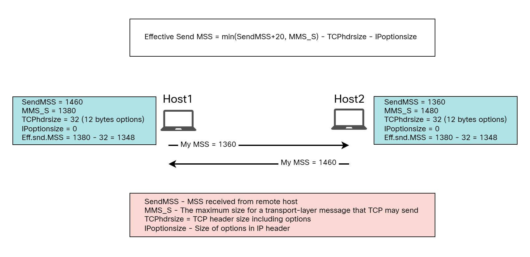
It may be a bit surprising that they both have an Effective Send MSS of 1348 bytes when Host2 is capable of 1448 bytes. However, because Host1 has an IP MTU of 1400 bytes, it can’t do more than 1348 even though Host2 would be capable of receiving it. How does a host know what value to use? This is covered in RFC 9293:
The maximum size of a segment that a TCP endpoint really sends, the “effective send MSS”, MUST be the smaller (MUST-16) of the send MSS (that reflects the available reassembly buffer size at the remote host, the EMTU_R [19]) and the largest transmission size permitted by the IP layer (EMTU_S [19]):
Eff.snd.MSS = min(SendMSS+20, MMS_S) – TCPhdrsize – IPoptionsize
where:
- SendMSS is the MSS value received from the remote host, or the default 536 for IPv4 or 1220 for IPv6, if no MSS Option is received.
- MMS_S is the maximum size for a transport-layer message that TCP may send.
- TCPhdrsize is the size of the fixed TCP header and any options. This is 20 in the (rare) case that no options are present but may be larger if TCP Options are to be sent. Note that some options might not be included on all segments, but that for each segment sent, the sender should adjust the data length accordingly, within the Eff.snd.MSS.
- IPoptionsize is the size of any IPv4 options or IPv6 extension headers associated with a TCP connection. Note that some options or extension headers might not be included on all packets, but that for each segment sent, the sender should adjust the data length accordingly, within the Eff.snd.MSS
It can be difficult to consume this text so let’s break it down by explaining all the terms:
- SendMSS – The MSS value received from the remote host. If no MSS option is received, use 536 bytes for IPv4 and 1220 bytes for IPv6.
- EMTU_R – In RFC 1122 defined as largest datagram size that can be reassembled (think fragmentation), but in practice, to avoid fragmentation, the largest datagram that can be received without fragmentation.
- EMTU_S – The maximum IP datagram size that may be sent.
- MMS_S – The maximum size for a transport-layer message that TCP may send.
- MMS_R – The maximum size for a transport-layer message that can be received (and reassembled at the IP layer).
Let’s calculate the Effective Send MSS for Host1 and Host2. Starting with Host1:
- SendMSS – 1460, as received from Host2.
- EMTU_R – 1400.
- EMTU_S – 1400.
- MMS_S – 1380.
- MMS_R – 1380.
- Effective Send MSS – min(SendMSS+20, MMS_S) – TCPhdrsize – IPoptionsize = min(1480, 1380) – 32 – 0 = 1348.
Now Host2:
- SendMSS – 1360, as received from Host1.
- EMTU_R – 1500.
- EMTU_S – 1500.
- MMS_S – 1480.
- MMS_R – 1480.
- Effective Send MSS – min(SendMSS+20, MMS_S) – TCPhdrsize – IPoptionsize = min(1380, 1480) – 32 – 0 = 1348.
To avoid fragmentation, the Effective Send MSS is always based on the minimum value of what we can locally do vs what the remote host can do. This means that unless a host is signaling a value less than their max, or that there is a third party altering the MSS, both sides would be using the same value for Effective Send MSS.
The process of calculating the Effective Send MSS is shown in the picture below:
MSS clamping
If all devices along a path has the same MTU, or PMTUD is able to run successfully, there shouldn’t be much issues with setting the right MSS in the TCP 3-way handshake. However, there are things that could affect the ability to perform PMTUD properly such as:
- Packets traversing an encrypted domain performing IPSec.
- Other forms of tunneling such as GRE.
- Packets traversing a MPLS domain.
- Devices filtering ICMP messages.
When PMTUD can’t be performed, you’ll end up with either fragmented packets, dropped packets, or both. Rather than trying to change the MTU on the host itself, which is tedious and error prone, an intermediate device can inspect TCP packets and modify the MSS that is signaled to a value that fits within the MTU of the path. For example, if there is encryption and tunneling, you may lose close to a 100 bytes in some scenarios and many people would configure a MTU of 1400 and MSS of 1360 in such scenarios. Let’s take a closer look at MSS clamping.
MSS clamping has the following characteristics:
- It’s configured on IP interfaces such as routed interfaces, subinterfaces, SVIs, or any other L3 interface.
- It inspects incoming and outgoing TCP packets with SYN flag set and modifies the MSS.
- This only works for TCP as there is no mechanism in UDP to signal a segment size.
Because MSS clamping modifies both incoming and outgoing MSS, it doesn’t matter so much what device that performs it. If it’s closer to the source or closer to the destination. Let’s try to configure MSS clamping in our lab. I’ve restored the MTU on Host1 to be 1500:
cisco@Host1:~$ ip addr | grep mtu
2: ens2: <BROADCAST,MULTICAST,UP,LOWER_UP> mtu 1500 qdisc fq_codel state UP group default qlen 1000
I’m going to configure MSS clamping on R1 towards Host1:
R1(config)#int gi1
R1(config-if)#ip tcp adjust-mss 1360
Now I’ll run an iPerf test and capture the TCP packets at the different interfaces to see how MSS is modified. First, Host2 is sending a SYN with a MSS of 1460:
Frame 2: 74 bytes on wire (592 bits), 74 bytes captured (592 bits)
Ethernet II, Src: 52:54:00:1a:02:24, Dst: 52:54:00:11:6b:ae
Internet Protocol Version 4, Src: 10.0.1.10, Dst: 10.0.0.10
Transmission Control Protocol, Src Port: 38344, Dst Port: 5201, Seq: 0, Len: 0
    Source Port: 38344
    Destination Port: 5201
    [Stream index: 0]
    [Stream Packet Number: 1]
    [Conversation completeness: Incomplete, DATA (15)]
    [TCP Segment Len: 0]
    Sequence Number: 0    (relative sequence number)
    Sequence Number (raw): 3444096230
    [Next Sequence Number: 1    (relative sequence number)]
    Acknowledgment Number: 0
    Acknowledgment number (raw): 0
    1010 .... = Header Length: 40 bytes (10)
    Flags: 0x002 (SYN)
    Window: 64240
    [Calculated window size: 64240]
    Checksum: 0x4bb9 [unverified]
    [Checksum Status: Unverified]
    Urgent Pointer: 0
    Options: (20 bytes), Maximum segment size, SACK permitted, Timestamps, No-Operation (NOP), Window scale
        TCP Option - Maximum segment size: 1460 bytes
        TCP Option - SACK permitted
        TCP Option - Timestamps: TSval 3160538007, TSecr 0
        TCP Option - No-Operation (NOP)
        TCP Option - Window scale: 7 (multiply by 128)
    [Timestamps]
After the packet has traversed R1, the MSS is now set to 1360:
Frame 1: 74 bytes on wire (592 bits), 74 bytes captured (592 bits)
Ethernet II, Src: 52:54:00:1b:58:2f, Dst: 52:54:00:11:fc:84
Internet Protocol Version 4, Src: 10.0.1.10, Dst: 10.0.0.10
Transmission Control Protocol, Src Port: 38344, Dst Port: 5201, Seq: 0, Len: 0
    Source Port: 38344
    Destination Port: 5201
    [Stream index: 0]
    [Stream Packet Number: 1]
    [Conversation completeness: Incomplete, DATA (15)]
    [TCP Segment Len: 0]
    Sequence Number: 0    (relative sequence number)
    Sequence Number (raw): 3444096230
    [Next Sequence Number: 1    (relative sequence number)]
    Acknowledgment Number: 0
    Acknowledgment number (raw): 0
    1010 .... = Header Length: 40 bytes (10)
    Flags: 0x002 (SYN)
    Window: 64240
    [Calculated window size: 64240]
    Checksum: 0x4c1d [unverified]
    [Checksum Status: Unverified]
    Urgent Pointer: 0
    Options: (20 bytes), Maximum segment size, SACK permitted, Timestamps, No-Operation (NOP), Window scale
        TCP Option - Maximum segment size: 1360 bytes
        TCP Option - SACK permitted
        TCP Option - Timestamps: TSval 3160538007, TSecr 0
        TCP Option - No-Operation (NOP)
        TCP Option - Window scale: 7 (multiply by 128)
    [Timestamps]
Host1 then responds with the SYN, ACK with a MSS of 1460:
Frame 2: 74 bytes on wire (592 bits), 74 bytes captured (592 bits)
Ethernet II, Src: 52:54:00:11:fc:84, Dst: 52:54:00:1b:58:2f
Internet Protocol Version 4, Src: 10.0.0.10, Dst: 10.0.1.10
Transmission Control Protocol, Src Port: 5201, Dst Port: 38344, Seq: 0, Ack: 1, Len: 0
    Source Port: 5201
    Destination Port: 38344
    [Stream index: 0]
    [Stream Packet Number: 2]
    [Conversation completeness: Incomplete, DATA (15)]
    [TCP Segment Len: 0]
    Sequence Number: 0    (relative sequence number)
    Sequence Number (raw): 1838945938
    [Next Sequence Number: 1    (relative sequence number)]
    Acknowledgment Number: 1    (relative ack number)
    Acknowledgment number (raw): 3444096231
    1010 .... = Header Length: 40 bytes (10)
    Flags: 0x012 (SYN, ACK)
    Window: 65160
    [Calculated window size: 65160]
    Checksum: 0x1b79 [unverified]
    [Checksum Status: Unverified]
    Urgent Pointer: 0
    Options: (20 bytes), Maximum segment size, SACK permitted, Timestamps, No-Operation (NOP), Window scale
        TCP Option - Maximum segment size: 1460 bytes
        TCP Option - SACK permitted
        TCP Option - Timestamps: TSval 1915172417, TSecr 3160538007
        TCP Option - No-Operation (NOP)
        TCP Option - Window scale: 7 (multiply by 128)
    [Timestamps]
    [SEQ/ACK analysis]
After the packet traverses R1, the MSS is modified to 1360:
Frame 3: 74 bytes on wire (592 bits), 74 bytes captured (592 bits)
Ethernet II, Src: 52:54:00:11:6b:ae, Dst: 52:54:00:1a:02:24
Internet Protocol Version 4, Src: 10.0.0.10, Dst: 10.0.1.10
Transmission Control Protocol, Src Port: 5201, Dst Port: 38344, Seq: 0, Ack: 1, Len: 0
    Source Port: 5201
    Destination Port: 38344
    [Stream index: 0]
    [Stream Packet Number: 2]
    [Conversation completeness: Incomplete, DATA (15)]
    [TCP Segment Len: 0]
    Sequence Number: 0    (relative sequence number)
    Sequence Number (raw): 1838945938
    [Next Sequence Number: 1    (relative sequence number)]
    Acknowledgment Number: 1    (relative ack number)
    Acknowledgment number (raw): 3444096231
    1010 .... = Header Length: 40 bytes (10)
    Flags: 0x012 (SYN, ACK)
    Window: 65160
    [Calculated window size: 65160]
    Checksum: 0x1bdd [unverified]
    [Checksum Status: Unverified]
    Urgent Pointer: 0
    Options: (20 bytes), Maximum segment size, SACK permitted, Timestamps, No-Operation (NOP), Window scale
        TCP Option - Maximum segment size: 1360 bytes
        TCP Option - SACK permitted
        TCP Option - Timestamps: TSval 1915172417, TSecr 3160538007
        TCP Option - No-Operation (NOP)
        TCP Option - Window scale: 7 (multiply by 128)
    [Timestamps]
    [SEQ/ACK analysis]
We can see that the Ethernet frames when the transfer begins are 1414 bytes as expected:
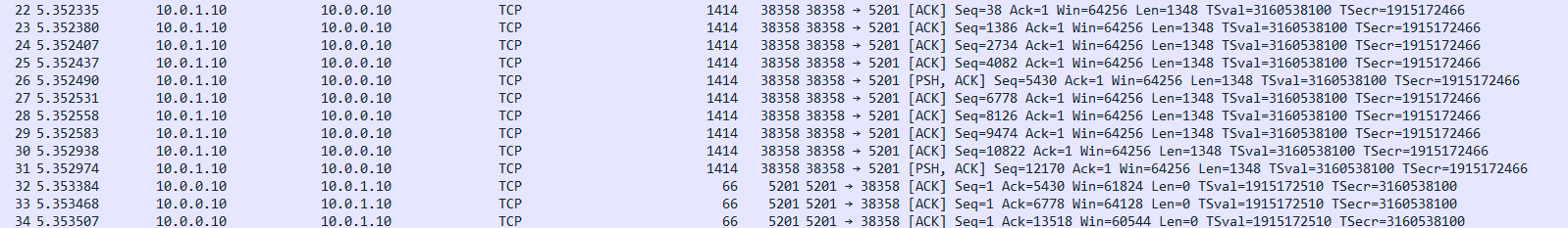
The process of MSS clamping is shown in the diagram below:
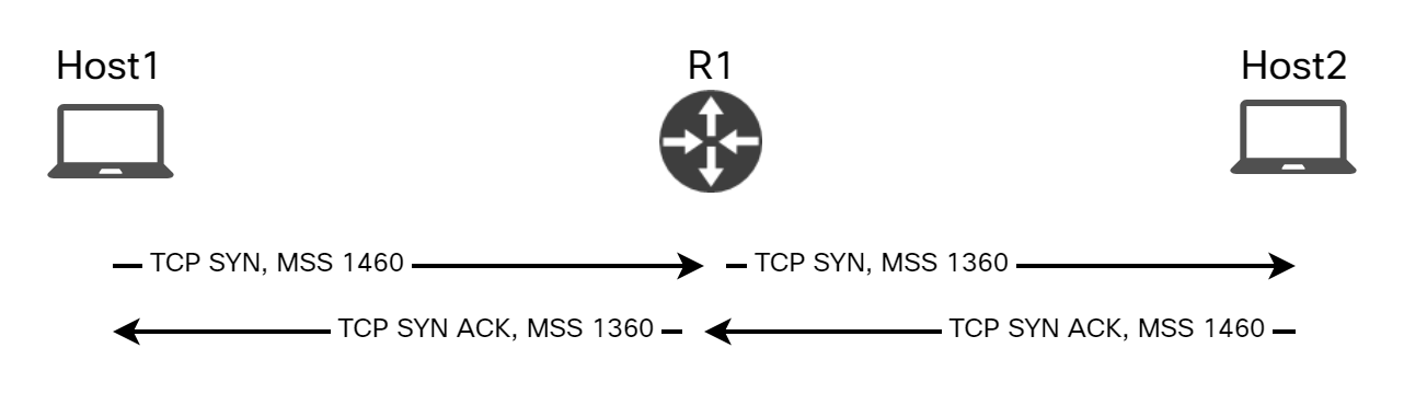
MSS clamping works well for most scenarios. One interesting scenario to consider is what happens if a host is configured with a lower MTU than the router, and hence will advertise a lower MSS. Let’s try by setting the MTU to 1300 on Host1:
cisco@Host1:~$ sudo ip link set dev ens2 mtu 1300
cisco@Host1:~$ ip addr | grep mtu
2: ens2: <BROADCAST,MULTICAST,UP,LOWER_UP> mtu 1300 qdisc fq_codel state UP group default qlen 1000
I’ll run iPerf again and then we’ll see what MSS Host2 is receiving from Host1:
Frame 2: 74 bytes on wire (592 bits), 74 bytes captured (592 bits)
Ethernet II, Src: 52:54:00:11:6b:ae, Dst: 52:54:00:1a:02:24
Internet Protocol Version 4, Src: 10.0.0.10, Dst: 10.0.1.10
Transmission Control Protocol, Src Port: 5201, Dst Port: 32770, Seq: 0, Ack: 1, Len: 0
    Source Port: 5201
    Destination Port: 32770
    [Stream index: 0]
    [Stream Packet Number: 2]
    [Conversation completeness: Incomplete, DATA (15)]
    [TCP Segment Len: 0]
    Sequence Number: 0    (relative sequence number)
    Sequence Number (raw): 2178938487
    [Next Sequence Number: 1    (relative sequence number)]
    Acknowledgment Number: 1    (relative ack number)
    Acknowledgment number (raw): 1024038407
    1010 .... = Header Length: 40 bytes (10)
    Flags: 0x012 (SYN, ACK)
    Window: 64896
    [Calculated window size: 64896]
    Checksum: 0x69d0 [unverified]
    [Checksum Status: Unverified]
    Urgent Pointer: 0
    Options: (20 bytes), Maximum segment size, SACK permitted, Timestamps, No-Operation (NOP), Window scale
        TCP Option - Maximum segment size: 1260 bytes
        TCP Option - SACK permitted
        TCP Option - Timestamps: TSval 1917811764, TSecr 3163177353
        TCP Option - No-Operation (NOP)
        TCP Option - Window scale: 7 (multiply by 128)
    [Timestamps]
    [SEQ/ACK analysis]
It’s 1260! Meaning that the MSS was not adjusted by the router because the value was lower than what the router would modify it to.
Summary
In this post we learned about different protocols such as Ethernet, IP, and TCP. How much overhead do they add? How can we discover the MTU of a path using PMTUD? How do we signal in TCP how large segments can be received? What can we do when PMTUD doesn’t work reliably such as with devices filtering ICMP? We learned that MSS clamping can be used to modify the MSS value of TCP SYN and SYN ACK packets. In another post we’ll look at an interesting scenario revolving around MTU and MPLS.
Yesterday, during an interview, I discussed with someone about MSS, and I was not very confident in my answers because of my lack of deep knowledge of how TCP works.
I found this article very useful, and it fills some of the gaps that I have.
Thank you, Daniel! 🙂
Happy to hear that! Thanks!
Excellent, looking forward for more topics.
Thank you!
Really useful, thank you!
Love it big fan of the blog and its updates
Thanks, Rob!
as usual, great
Thanks!
Thanks a lot Daniel for this informative and detailed explanation. Really appreciate the time and effort that you put into document all these scenarios. Your posts and observations help a lot.
Regarding the MSS clamping, one possible scenario that ‘could’ cause issues (if my understanding is correct) would be in the scenario where there is asymmetric path between host1 and host2. Suppose host1 and host2 are configured with default 1500 MTU and the R1 has tcp mss adjust set to 1360 towards the host1 interface. R2 doesn’t have the configs for MSS clamping present in it. In this scenario, suppose host1 takes the path via R1 to reach host2, and host2 would take the path via R2 to reach host2. In this case when host1 sends SYN, host2 will receive MSS 1360, but when host1 initiate traffic, host1 will receive MSS 1460.
Let’s calculate the Effective Send MSS for Host1 and Host2. Starting with Host1:
SendMSS – 1460, as received from Host2.
EMTU_R – 1500
EMTU_S – 1500.
MMS_S – 1480.
MMS_R – 1480.
Effective Send MSS – min(SendMSS+20, MMS_S) – TCPhdrsize – IPoptionsize = min(1480, 1480) – 32 – 0 = 1448.
Now Host2:
SendMSS – 1360, as received from Host1.
EMTU_R – 1500.
EMTU_S – 1500.
MMS_S – 1480.
MMS_R – 1480.
Effective Send MSS – min(SendMSS+20, MMS_S) – TCPhdrsize – IPoptionsize = min(1380, 1480) – 32 – 0 = 1348.
(please correct me if my calculations are wrong:)). So in this case, there will be a misunderstanding on the agreed MSS values between host1& host2 that can cause issues. It would be worth testing this in the lab.
+———————-R1————————+
host 1 ——-| |———-host2
+———————-R2————————+
Thanks, George! Appreciate it!
Asymmetric routing can definitely be a factor in potential MTU issues and what MSS gets advertised. If MSS clamping is enabled on the interface towards Host1, then it should affect both what MSS others see from Host1 as well as what Host1 sees from others as clamping affects both the incoming and outgoing TCP SYN segments. This means that as long as clamping is enabled on the interface towards Host1, there shouldn’t be any issues.
Now, if clamping is applied further upstream from Host1, not on the interface towards Host1, then you could definitely have the scenario you’re describing where MSS in one direction is one value and MSS in the other direction is another value.
I’ll have to try it in a lab to be certain, but that’s what I anticipate.
Thank you for commenting and giving me the idea for a new blog post. I think this would be an excellent scenario to cover to show the potential pitfalls of MSS and MSS clamping.
I just share my couple of things.
1. Your calculating of sending MSS on both side is correct.
2. TCP-MSS adjustment is only take effect with SYN-flag set. That value is used for the receing end for decide what MSS it should use when encapsulate a IP datagram and send data.
3. TCP-MSS is doing on the intermidiate router and it not equal to the router’s IP MTU, actually it has nothing to do with it.
4. At the end of the day, once both side got the MSS calculated, encapsulate packet, its the IP MTU decide whether it need fragmentation or drop.
5. It is fine you got data with MSS 1460 while the Router got tcp-mss 1360, as long as the IP datagram is not oversize the Router’s MTU.
In your LAB setup, let’s consider a real usecase. Say R1Host2 got GRE segment, you want Host1 sending traffic to Host2 not be fragmented, then you expected Host1 using smaller MSS when sending traffic. To do that, you need make Host1 to calculate the smaller MSS during SYN exchange, how can you achieve that? You need set the ip tcp-mss adjustment on R2, that way when R1 receive SYN from Host2, it will decide a smaller MSS. That way when Host 1 send traffic to Host2 the encapsulated IP datagram will have a smaller MTU and it will have no problem(no fragment) to pass the GRE segment between R1 and Host2.
Another great blog post – really interseting deep dive.
Thank You!
Absolutely fantastic coverage of these concepts. I like the case highlighted by George on Asymmetric routing and look forward to more insights from your forthcoming blog on this scenario.
Absolutely fantastic coverage of these concepts. I like the case highlighted by George on Asymmetric routing and look forward to more insights from your forthcoming blog on this scenario.
This is one of the best written articles on the subject I’ve seen. Writing about fundamentals is often overlooked but with a continuous conveyor belt of new engineers coming into the profession posts like this are invaluable.
Thanks, Ian! Doing my best to give people access to solid articles on the fundamentals.
Excellent write up as always. Thanks Daniel.
Thanks, Chris!
Thank you for the amazing article, Daniel.
I have one question with an interesting problem that I encountered.
I have a GRE tunnel on 2 routers. These tunnels have “ip mtu 3800” because our transport can support it. We’ve had no issues, up until one of the engineers decided to put “ip tcp adjust-mss 1360” on the tunnel.
When the engineer did that, the sys admins were complaining that their data transfer speeds were around 80-90% slower than before. After some digging around, we removed the tcp adjust-mss comand from the tunnel, and their backup speeds were back to normal.
Can you explain what is possibly happening here? Trying to find out why the backups are slowing down when we introduce the tcp-adjust command on the tunnel.
That’s an interesting scenario!
I don’t believe the impact is from the smaller TCP segments. At first I considered if the impact was from having to rewrite the MSS, but MSS is only signaled in SYN and not for every TCP segment, so that doesn’t sound feasible either. I would assume that the TCP session would live until the transfer is complete.
This could be something that is related to the platform and software you are running. It would be interesting to look at a packet capture to compare the two scenarios.
Hi Daniel, Effective Send MSS = MTU – Eth Header – IP Header with Options – TCP Header with Options. Is it true in all scenarios? or we have to calculate based on the formula listed above.
Hi,
Ethernet header is not part of the calculation as it’s added after L4 and L3. Normally, IP MTU would be 1500 bytes. If using no TCP or IP options, 40 bytes will be consumed by L4 and L3 headers, 20 bytes each, leaving 1460 bytes for actual data. MSS can be different for different destinations, though. In theory, some sessions could use certain TCP options, for example, while others wouldn’t.
Crisp, Clear and Precise details…!!
Such a quality blog post!
Thanks!
I spend over 1 hour just try to understand your detail expenation about MSS MTU. You provide so much useful yet clean content for some most confusion concepts. I really enjoy it when I was reading.
Now I am going to spend another 2 hours or more just do some LAB test, this post deserves everyone no matter he/she is a entry level or expert level to go through it lab it.
Thank you SO MUCH!
Thanks a lot, Joshua! Appreciate it 🙂
Thank you! Until now, I’ve seen several articles which purport to explain MSS clamping… without really explaining it. This article does a brilliant job.
I’ve seldom seen such clear and detailed writing since reading the books by W. Richard Stevens, and that was many years ago.
That is some praise. Truly appreciated. Thank you, Graeme!