In 1000BASE-T Part 1, we reviewed the layers and what their purpose is. Now we’re going to go much deeper into the layers that relate to the PHY, which is PCS, PMA, and Autonegotiation. First though, let’s review the objectives of 1000BASE-T:
- Support the CSMA/CD MAC.
- Comply with specifications for GMII (Clause 35).
- Support 1000 Mbit/s repeater (Clause 41).
- Provide line transmission support full and half duplex operation.
- Meet or exceed FCC Class A/CISPR or better operation.
- Support operation over 100 meters of copper balanced cabling (defined in 40.7).
- Bit Error Ratio less than or equal to 10^-10.
- Support Auto negotiation (Clause 28).
How does 1000BASE-T achieve a bandwidth of 1000 Mbit/s? As you probably know, the twisted pair cable consists of four pairs, eight wires in total, where transmit and receive are separated to achieve full duplex operation:
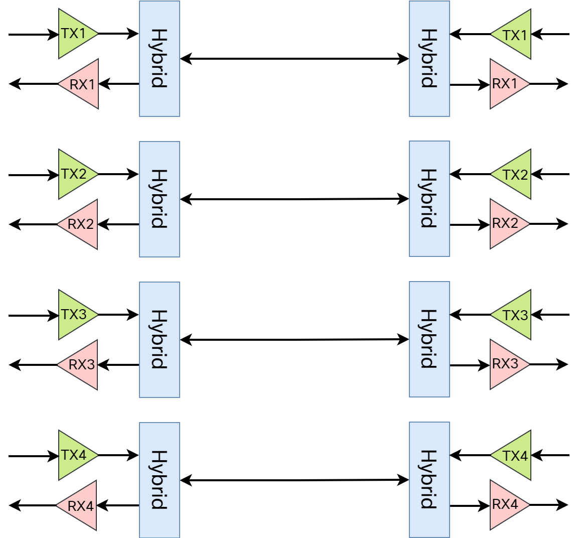
The meaning of hybrid in this context is that transmit and receive is performed on the same pair. Every pair is capable of 250 Mbit/s data rate, for a total of 1000 Mbit/s. As PAM-5 encoding is used (more on this later), the baud rate is 125 MHz. This means that the PHY receives 8-bit words to send every 8 nano seconds.
What does 1000BASE-T need to do to operate?
- Maintain timing synchronization between leader/follower.
- Successfully receive signals on four pairs at 125 Mbaud.
- Successfully perform the following within those timing constraints (8 nano seconds):
- Remove Inter Symbol Interference (ISI) through equalization.
- Remove Echo from near-end transmitter and its channel reflection.
- Remove Near-End Cross Talk (NEXT) from the three local pairs.
- Remove Far-End Cross Talk (FEXT) from the three remote pairs.
- Recover the correct code group from the 4D-PAM5 signals recovered.
- Using a Viterbi decoder.
- Descramble the recovered code group.
Establishing a 1000 Mbit/s link and maintaining it involves a lot of components and logic. To combat the issues with Echo, NEXT, etc., there are several components in the PHY:
- Feed Forward Equalizer (FFE).
- Decision Feedback Equalizers (DFE).
- Echo Canceller.
- NEXT Canceller.
- FEXT Canceller.
Think of these as filters that take the full signal including interference, echo etc., and filter that to have a “cleaner” signal.
Startup
When the link is first established, there are several tasks that need to be performed:
- Negotiation of speed and duplex through Auto negotiation.
- Establish what side is the leader and what side is the follower.
- Acquire timing (on the follower side).
- Train adaptive equalizers.
- Train equalizers (DFE, FFE).
- Train noise cancellers (Echo, NEXT, FEXT).
- Synchronize scramblers.
The startup sequence uses as sequenced approach in three steps where the leader and follower perform different tasks such as training the ECHO canceller, DFE, adjusting phase, acquiring time (follower), and so on. There are timers involved in the startup, minwait and maxwait, that defines the minimum and amount of time that the transceiver is in training mode.
PCS
The Physical Coding Sublayer (PCS) characteristics:
- It is the interface between GMII and PMA.
- It transmits 8-bit code groups in parallell at 125 MHz for PMA to serialize.
- It translates the data to be sent in a suitable form.
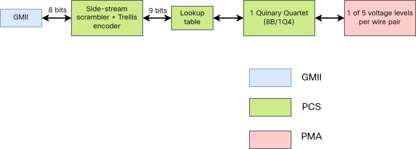
- It passes 4D 5-level (+2, +1, 0, -1, -2) coding to the PMA to convert to electrical signaling.
The diagram below shows the flow from GMII to what gets output via the PMA:

Scrambling
What is scrambling and why do we need it? What is a Trellis encoder? Scrambling in the context of 1000BASE-T is not used to make the receiver’s job more difficult, but rather to combat issues related to the channel between the transmitter and receiver. Without scrambling, some data would consistently produce the highest frequency waveform on the channel. Higher frequency waveforms tend to radiate better. Other data patterns would consistently produce low frequency waveforms, making it difficult for the follower to recover the timing information. Scrambling is used to spread power over a range in the frequency spectrum, often referred to as spread spectrum. This better utilizes the channel to make more efficient use of the bandwidth. Scrambling also helps the receiver to separate noise from signal.
How do you scramble data? You take each symbol and alter it with a random value! However, using a truly random value would not allow for descrambling, which means that a pseudo-random value must be used. The pseudo-random value appears to be random, but is actually periodic. One way of generating pseudo-random values is by using a Linear Feedback Shift Register (LFSR). For the receiver to be able to descramble, it must synchronize the descrambler. The state of the LSFR is transmitted, typically in idle mode. A side-stream scrambler is one way of implementing the LFSR:
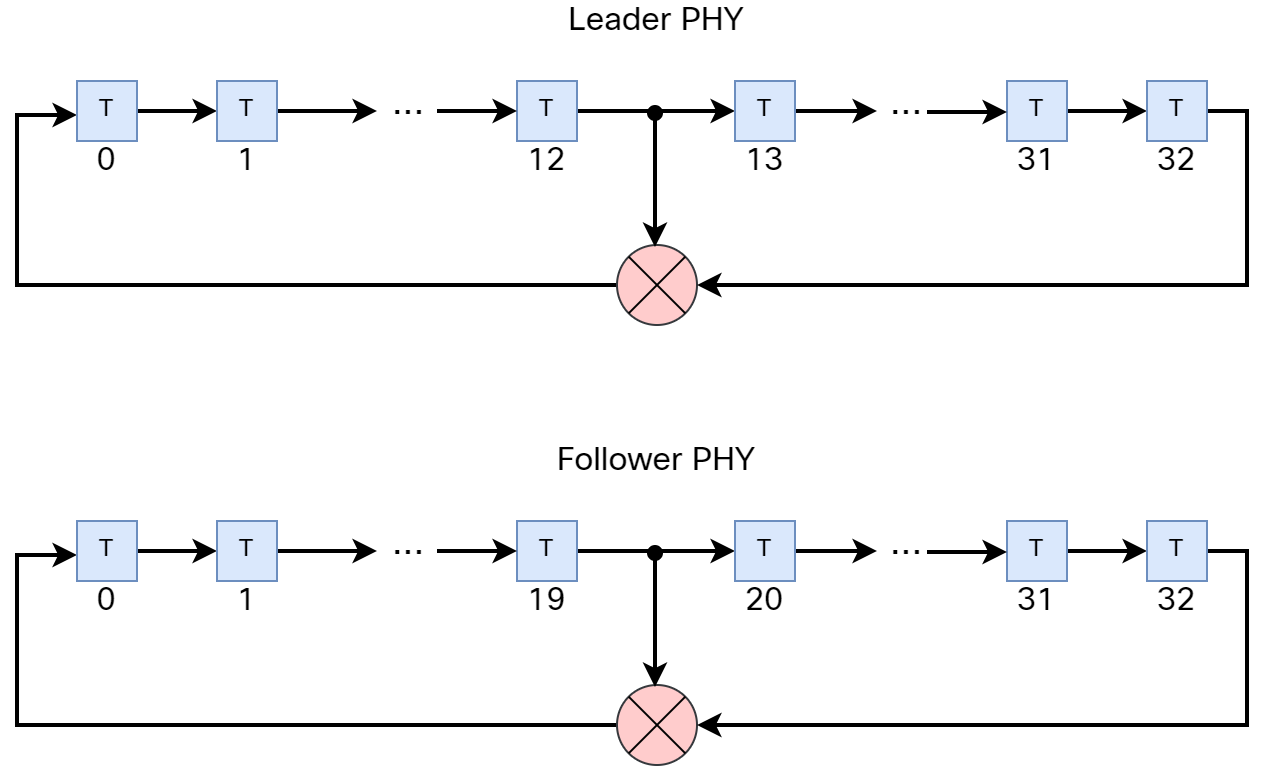
The scramblers above use 33 bits. This means that it takes 2^33-1 bits before the pattern will repeat. Considering 8ns between the 8-bit words, it would take 68.72s before the pattern repeats.
Trellis encoding
100BASE-T uses a 3-level encoding while 1000BASE-T uses a 5-level encoding. Hence, 1000BASE-T is more complex and this means that 1000BASE-T needs 6 dB more Signal to Noise Ratio (SNR) than 100BASE-T does. To combat this, Forward Error Correction (FEC) is implemented using Trellis encoding and Viterbi decoding regaining the 6 dB.
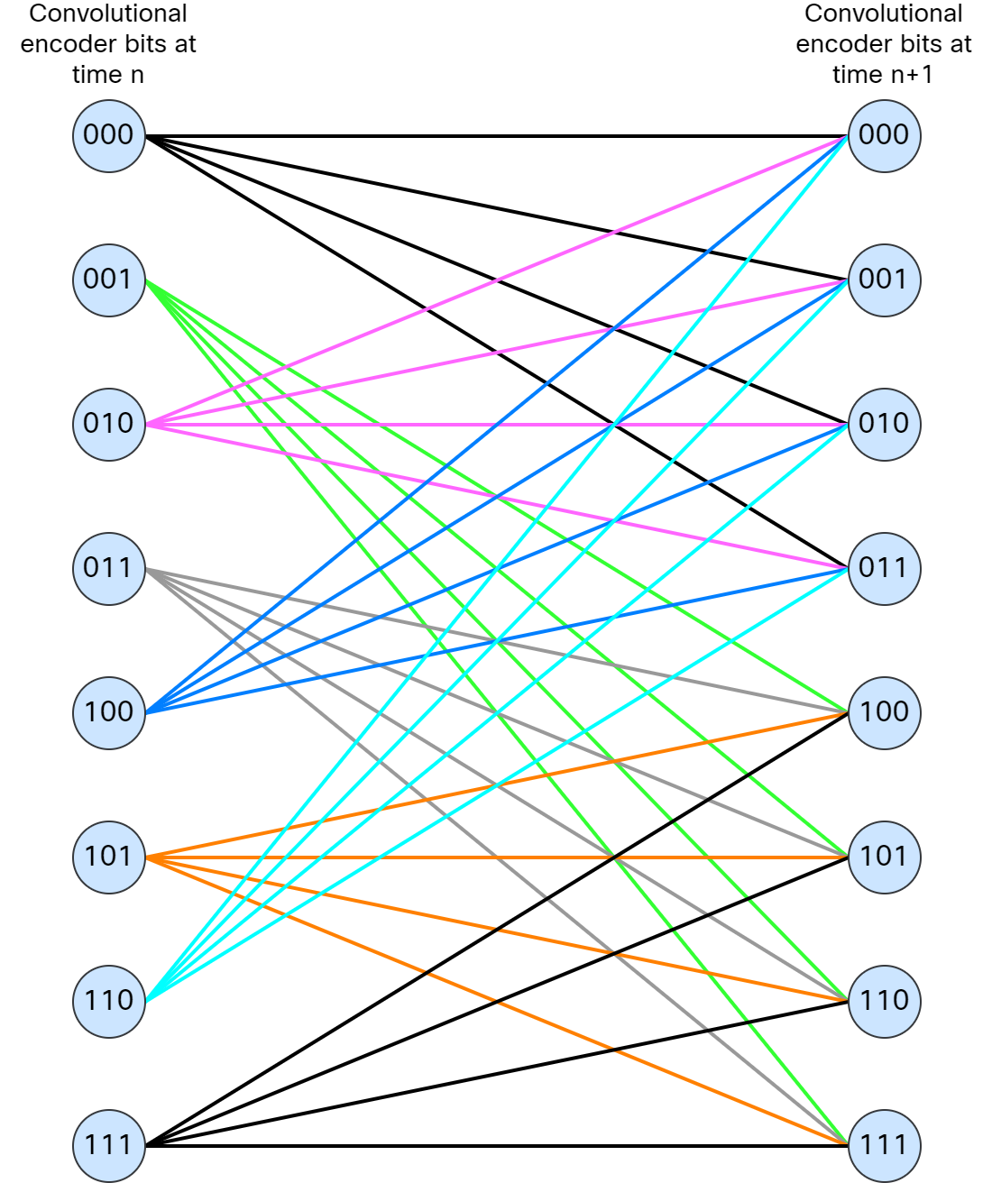
Now, apparently three years of university studies wasn’t enough for me to understand all the math of Trellis encoding, but essentially stream of 8-bit words that come from the scrambler are combined to produce a 9th bit by a convolutional encoder. These 9 bits are used to then lookup a mapping by set partitioning. Out of the 9 bits, 3 bits are used to find the subset index. The remaining 6 bits are used to select the points within the subset. This generates a limited amount of permissible paths as shown below, which can be used to overcome noise events:
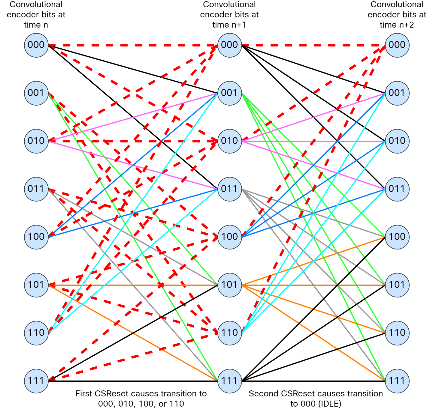
When there is no data, IDLE (000) is sent. To make IDLE easily detectable, it has its own symbol, and the convolutional decoder is reset on IDLE. To get back to the top of the diagram, CSReset is triggered two times. This is shown below:
Viterbi decoding
Viterbi decoding is used at the receiver to evaluate which path is most likely to have been selected by the Trellis (convolutional) encoder at the transmitter. This provides error correction and improves the required signal-to-noise ratio at the receiver, as opposed to simply providing error detection as a CRC or parity check might. This means that not only does it have the ability to detect errors, it can also correct them.
Once again, the full details of this is out of depth for me, but the Viterbi decoding can analyze the paths based on Trellis encoding to see whether code groups are using the correct path or not. It may recover the correct path, depending on how errored it was.
PMA
The PMA characteristics:
- The primary role is to serialize and de-serialize data to/from the MDI.
- It uses PAM-5, a voltage dependent signaling between MDI/PMA.
- It controls the transmit signal by a method called Partial Response.
The PCS sends the quinary symbols to the PMA which converts to PAM-5 signaling using 5 different voltage levels. Recall the image used earlier demonstrating this flow:
The five voltage levels are -1, -0.5, 0, 0.5, and 1 Volt. This allows for 2 bits per symbol. In reality, there are actually 17 different voltage levels because the PMA uses Partial Response which acts as a digital filter. Partial Response is the introduction of known intersymbol interference (ISI) by the digital filter applied to the PAM-5 symbol stream.
There are in total 6 subfunctions that the PMA is responsible for:
- PMA Reset.
- PMA Transmit.
- PMA Receive.
- PMA PHY Control.
- Link Monitor.
- Clock Recovery.
Based on the names, we can see that PMA transmits and receives symbols. Within the PMA Receive subfunction, there are some interesting primitives:
- Loc_rcvr_status.
- SCR_STATUS.
The Loc_rcvr_status is generated by PMA Receive to indicate the status of the receive link at the local PHY. The status of Loc_rcvr_status is conveyed to PCS Transmit, PCS Receive, PMA PHY Control, and Link Monitor to provide information on whether the status of the receive link is satisfactory or not.
SCR_STATUS is generated by PCS Receive to communicate the status of the descrambler for the local PHY. This is conveyed to PMA Receive to indicate if the descrambler has achieved synchronization.
Frame format
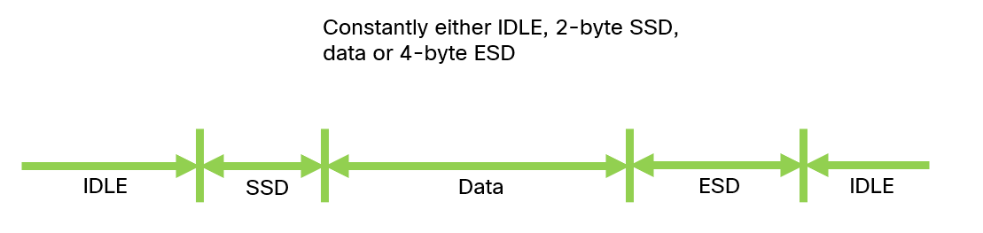
In the first post, I mentioned that a link is never really silent. There is always something being transmitted and/or received. The link will always have one of the following:
- IDLE.
- Start-of-Stream Delimiter (SSD).
- Data.
- End-of-Stream Delimiter (ESD).
This is shown below:
In the next post, we’ll take a deep dive into auto negotiation!
Very valuable informations and not seen this much details before..thanks
Thank you!
Doesn’t ethernet allow you to send and receive on the same wire in full-duplex and the other wire in the pair use the oppostive voltage to prevent internal interference?
In autonegotiation, how is the selection of leader follower done ?
This is defined in 40.5.2 in the standard. The devices generate a random seed number. If both devices want to be leader, for example, the side with the highest seed number would win and become the leader.
From IEEE 802.3:
“The method of generating a random or pseudorandom seed is left to the implementer. The generated random
seeds should belong to a sequence of independent, identically distributed integer numbers with a uniform
distribution in the range of 0 to 211– 2. The algorithm used to generate the integer should be designed to
minimize the correlation between the number generated by any two devices at any given time. A seed
counter shall be provided to track the number of seed attempts. The seed counter shall be set to zero at
startup and shall be incremented each time a seed is generated. When MASTER-SLAVE resolution is
complete, the seed counter shall be reset to 0 and bit 10.15 shall be set to logical zero. A MASTER-SLAVE
resolution fault shall be declared if resolution is not reached after the generation of seven seeds.”
Pingback: Weekend Reads 041224 – rule 11 reader