If you follow me on Twitter ( https://twitter.com/danieldibswe), you know I have been doing a lot of SD-WAN lately and I recently built my own lab. In this lab, I wanted to try a feature known as service chaining. What is service chaining? It’s a method of sending traffic through one or more services, such as a firewall, before the traffic takes the “normal” path towards its destination.
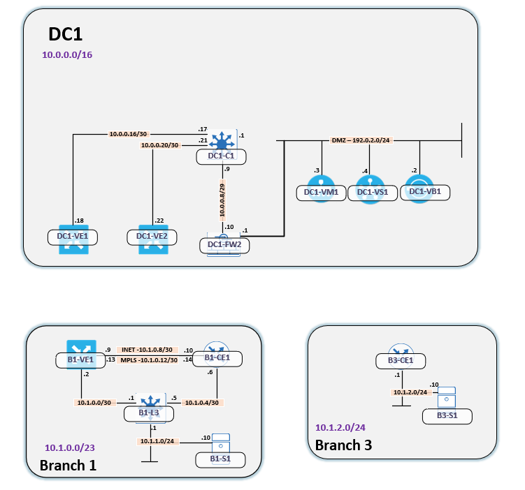
Before we dive deeper in, let me show the topology in use:

When I tested this feature, the data plane was working perfectly but my traceroute looked very strange. The traceroute was also not finishing.
root@B1-S1:/# traceroute 10.1.2.10
traceroute to 10.1.2.10 (10.1.2.10), 30 hops max, 60 byte packets
 1  10.1.1.1 (10.1.1.1)  6.951 ms  36.355 ms  39.604 ms
 2  10.1.0.2 (10.1.0.2)  11.775 ms  15.047 ms  15.535 ms
 3  10.0.0.18 (10.0.0.18)  28.540 ms  28.538 ms  28.532 ms
 4  10.1.2.10 (10.1.2.10)  41.748 ms  41.746 ms  41.736 ms
 5  10.0.0.18 (10.0.0.18)  41.725 ms  42.090 ms  42.083 ms
 6  * * *
 7  * * *
There were a couple of things that confused me:
- Why is 10.0.0.18 in the trace?
- Why is 10.1.2.10, the destination, in hop 4 but then the trace continues
- Why is 10.0.0.18 once again in the trace?
- Why isn’t the traceroute finishing?
Before analyzing further, let’s take a look at the logical topology:

The expected traffic flow, when service chaining is enabled, is the following:
- B1-S1 to B1-L3
- B1-L3 to either B1-VE1 or B1-CE1 (ECMP)
- B1-VE1 or B1-CE1 to DC1-VE1 or DC1-VE2 (ECMP)
- DC1-VE1 or DC1-VE2 to DC1-FW2
- DC1-FW2 to DC1-VE1
- DC1-VE1 to B3-CE1
- B3-CE1 to B3-S1
There are multiple paths in the network, due to ECMP, which can, and will, cause asymmetric routing. What’s not part of the diagram here is two IPSec tunnels, one from each vEdge in the DC, towards the firewall. The firewall is using VTIs. Below is the IPSec configuration for these devices:
DC1-VE1:
interface ipsec1
   ip address 169.254.0.2/30
   tunnel-source-interface ge0/0
   tunnel-destination      172.16.0.2
   ike
    version      1
    mode         main
    rekey        14400
    cipher-suite aes128-cbc-sha1
    group        2
    authentication-type
     pre-shared-key
      pre-shared-secret $8$sWNh6R6uBvyhuUDznVJDjUmjeeId0i+cFC/3lqMVj0o=
     !
    !
   !
   ipsec
    rekey                   3600
    replay-window           512
    cipher-suite            aes256-cbc-sha1
    perfect-forward-secrecy group-2
   !
   no shutdown
  !
DC1-VE2:
interface ipsec1
  ip address 169.254.0.6/30
  tunnel-source-interface ge0/0
  tunnel-destination      172.16.0.2
  ike
   version      1
   mode         main
   rekey        14400
   cipher-suite aes128-cbc-sha1
   group        2
   authentication-type
    pre-shared-key
     pre-shared-secret $8$6fqSG94cmDceLmNKB/JPyvAhuzKTvk4EQfZqDcZoNS0=
    !
   !
  !
  ipsec
   rekey                   3600
   replay-window           512
   cipher-suite            aes256-cbc-sha1
   perfect-forward-secrecy group-2
  !
  no shutdown
 !
DC1-FW2:
ciscoasa# show run int tun1
!
interface Tunnel1
 nameif VEDGE-1
 ip address 169.254.0.1 255.255.255.252
 tunnel source interface outside
 tunnel destination 172.16.0.6
 tunnel mode ipsec ipv4
 tunnel protection ipsec profile VEDGE-1
ciscoasa# show run int tun2
!
interface Tunnel2
 nameif VEDGE-2
 ip address 169.254.0.5 255.255.255.252
 tunnel source interface outside
 tunnel destination 172.16.0.10
 tunnel mode ipsec ipv4
 tunnel protection ipsec profile VEDGE-2
ciscoasa# sh run route | i 10.1.2.0
route VEDGE-1 10.1.2.0 255.255.255.0 169.254.0.2 1
route VEDGE-2 10.1.2.0 255.255.255.0 169.254.0.6 2
There is some more IPSec configuration on the ASA but we don’t need to review that part of the configuration.
As we analyze the traceroute, there are some things we need to keep in mind:
- Traceroute results can be difficult to interpret and may not show what is actually going on in the data plane
- This is especially true for ICMP packets, that may be handled in the control plane of the device responding
- The two most common types of traceroute use either UDP or ICMP. We will see why this matters
- As explained earlier, the traceroute may not look as expected. This could be due to asymmetric routing
- ICMP may not be sourced from the same interface that data plane traffic is traveling through
For a good introduction to troubleshooting with traceroute, I recommend this talk by Steenbergen
Refer back to the logical topology above to follow along in the traceroute. The host I’m sourcing the traceroute from is some form of Linux distribution in the form of a Docker node in EVE-NG:
root@B1-S1:/# uname -a
Linux B1-S1 4.20.17-eve-ng-ukms+ #2 SMP Wed Jun 5 08:18:06 CEST 2019 x86_64 x86_64 x86_64 GNU/Linux
root@B1-S1:/#
Why is this important? Most Linux distributions, and also most networking devices, such as Cisco routers, use UDP by default when using traceroute, while Windows generally uses ICMP.
Our first hop in the traceroute is below:
1 10.1.1.1 (10.1.1.1) 6.951 ms 36.355 ms 39.604 ms
This is obvious as B1-S1 only has one path towards B3-S1 and that is via B1-L3.
The next hop was this one:
2 10.1.0.2 (10.1.0.2) 11.775 ms 15.047 ms 15.535 ms
Note that this could have been 10.1.0.6, if B1-L3 had used the other ECMP route towards one of the Edge devices. In this case, it sent the traffic to B1-VE1.
The third hop was this:
3 10.0.0.18 (10.0.0.18) 28.540 ms 28.538 ms 28.532 ms
This is where it can start to get a bit confusing. The IP address of 10.0.0.18 belongs to DC1-VE1. That much is clear. However, traffic should not be traversing this interface. Traffic should be using the ipsec1 interface towards DC1-FW1. This interface has an IP address of 169.254.0.2. Remember what I said about not blindly trusting traceroute? And that ICMP packets may not always be sourced from the interface we expect? This IP address is located in the correct VPN. For whatever reason, this is the address that the vEdge decided to source the ICMP time exceeded packet from. Perhaps there is a limitation on sourcing ICMP packets from an IPSec interface? I don’t know. The ICMP packet was sourced from 10.0.0.18 but traffic never actually traverses that interface. I confirmed this by doing a packet capture in the ASA.
ciscoasa# sh cap
capture traceroute type raw-data interface transit [Capturing - 0 bytes]
  match ip any host 10.1.2.10
It is clear that the packet is not going across the firewall’s transit interface, the one with an IP address of 10.0.0.9.
Now the real weirdness begins. Our fourth hop was the following:
4 10.1.2.10 (10.1.2.10) 41.748 ms 41.746 ms 41.736 ms
My friend Peter Palúch was quick to realize that there was something strange with hop four. Why?
- The traceroute did not end with this hop even though it is supposed to be the end destination
- The ICMP packet, when we viewed it in a capture, showed a different TTL than what B3-S1 was using when generating IP packets
But before I explain that further, why is my traceroute not ending?
How does a traceroute know that is has finished? Generally speaking, without me knowing the source code of traceroute, it will expect to get one of the following from the destination:
- An ICMP Port Unreachable, Type 3 Code 3 message
- An ICMP Echo Reply
When UDP is used, the destination will respond with Port Unreachable because that port is not open on the host. If using ICMP, the host will respond with Echo Reply.
Considering that I’m tracing with UDP, I am not receiving a Port Unreachable back from B3-S1. Why is this? It didn’t take long for me to realize that the firewall was dropping the ICMP Port Unreachable message from B3-S1 destined to B1-S1. The question was just why. I was using VTIs and these interfaces don’t do any filtering by default. I also tried to apply an access-list specifically permitting all traffic. I also played around with the “icmp inspect errors” command but I just couldn’t get the FW to allow the traffic back through.
After reviewing logs after enabling “logging console 7”, I saw these messages:
%ASA-7-609001: Built local-host VEDGE-1:10.1.1.10
%ASA-7-609001: Built local-host VEDGE-1:10.1.2.10
%ASA-6-302015: Built inbound UDP connection 917013 for VEDGE-1:10.1.1.10/53648 (10.1.1.10/53648) to VEDGE-1:10.1.2.10/33443 (10.1.2.10/33443)
%ASA-6-302020: Built inbound ICMP connection for faddr 10.1.2.10/0 gaddr 10.1.1.10/0 laddr 10.1.1.10/0 type 11 code 0
%ASA-6-302015: Built inbound UDP connection 917015 for VEDGE-1:10.1.1.10/34329 (10.1.1.10/34329) to VEDGE-1:10.1.2.10/33444 (10.1.2.10/33444)
%ASA-6-302015: Built inbound UDP connection 917016 for VEDGE-1:10.1.1.10/49824 (10.1.1.10/49824) to VEDGE-1:10.1.2.10/33445 (10.1.2.10/33445)
%ASA-6-302015: Built inbound UDP connection 917017 for VEDGE-1:10.1.1.10/43629 (10.1.1.10/43629) to VEDGE-1:10.1.2.10/33446 (10.1.2.10/33446)
%ASA-6-302015: Built inbound UDP connection 917018 for VEDGE-1:10.1.1.10/37688 (10.1.1.10/37688) to VEDGE-1:10.1.2.10/33447 (10.1.2.10/33447)
%ASA-6-302015: Built inbound UDP connection 917019 for VEDGE-1:10.1.1.10/54757 (10.1.1.10/54757) to VEDGE-1:10.1.2.10/33448 (10.1.2.10/33448)
%ASA-6-302015: Built inbound UDP connection 917020 for VEDGE-1:10.1.1.10/36266 (10.1.1.10/36266) to VEDGE-1:10.1.2.10/33449 (10.1.2.10/33449)
%ASA-6-302015: Built inbound UDP connection 917021 for VEDGE-1:10.1.1.10/49165 (10.1.1.10/49165) to VEDGE-1:10.1.2.10/33450 (10.1.2.10/33450)
%ASA-6-302015: Built inbound UDP connection 917022 for VEDGE-1:10.1.1.10/45501 (10.1.1.10/45501) to VEDGE-1:10.1.2.10/33451 (10.1.2.10/33451)
%ASA-6-302015: Built inbound UDP connection 917023 for VEDGE-1:10.1.1.10/55314 (10.1.1.10/55314) to VEDGE-1:10.1.2.10/33452 (10.1.2.10/33452)
%ASA-6-302015: Built inbound UDP connection 917024 for VEDGE-1:10.1.1.10/55117 (10.1.1.10/55117) to VEDGE-1:10.1.2.10/33453 (10.1.2.10/33453)
%ASA-6-302015: Built inbound UDP connection 917025 for VEDGE-1:10.1.1.10/48575 (10.1.1.10/48575) to VEDGE-1:10.1.2.10/33454 (10.1.2.10/33454)
%ASA-6-302015: Built inbound UDP connection 917026 for VEDGE-1:10.1.1.10/45959 (10.1.1.10/45959) to VEDGE-1:10.1.2.10/33455 (10.1.2.10/33455)
%ASA-6-302015: Built inbound UDP connection 917027 for VEDGE-1:10.1.1.10/48271 (10.1.1.10/48271) to VEDGE-1:10.1.2.10/33456 (10.1.2.10/33456)
%ASA-6-302015: Built inbound UDP connection 917028 for VEDGE-1:10.1.1.10/50888 (10.1.1.10/50888) to VEDGE-1:10.1.2.10/33457 (10.1.2.10/33457)
%ASA-7-609001: Built local-host VEDGE-1:172.16.0.18
%ASA-6-302020: Built inbound ICMP connection for faddr 172.16.0.18/0 gaddr 10.1.1.10/0 laddr 10.1.1.10/0 type 11 code 0
%ASA-7-609001: Built local-host VEDGE-2:10.1.2.10
%ASA-4-313005: No matching connection for ICMP error message: icmp src VEDGE-2:10.1.2.10 dst VEDGE-1:10.1.1.10 (type 3, code 3) on VEDGE-2 interface.  Original IP payload: udp src 10.1.1.10/55314 dst 10.1.2.10/33452.
%ASA-7-609002: Teardown local-host VEDGE-2:10.1.2.10 duration 0:00:00
%ASA-7-609001: Built local-host VEDGE-2:10.1.2.10
%ASA-4-313005: No matching connection for ICMP error message: icmp src VEDGE-2:10.1.2.10 dst VEDGE-1:10.1.1.10 (type 3, code 3) on VEDGE-2 interface.  Original IP payload: udp src 10.1.1.10/55117 dst 10.1.2.10/33453.
%ASA-7-609002: Teardown local-host VEDGE-2:10.1.2.10 duration 0:00:00
%ASA-7-609001: Built local-host VEDGE-2:10.1.2.10
%ASA-4-313005: No matching connection for ICMP error message: icmp src VEDGE-2:10.1.2.10 dst VEDGE-1:10.1.1.10 (type 3, code 3) on VEDGE-2 interface.  Original IP payload: udp src 10.1.1.10/48575 dst 10.1.2.10/33454.
%ASA-7-609002: Teardown local-host VEDGE-2:10.1.2.10 duration 0:00:00
%ASA-7-609001: Built local-host VEDGE-2:10.1.2.10
%ASA-4-313005: No matching connection for ICMP error message: icmp src VEDGE-2:10.1.2.10 dst VEDGE-1:10.1.1.10 (type 3, code 3) on VEDGE-2 interface.  Original IP payload: udp src 10.1.1.10/45959 dst 10.1.2.10/33455.
%ASA-7-609002: Teardown local-host VEDGE-2:10.1.2.10 duration 0:00:00
%ASA-7-609001: Built local-host VEDGE-2:10.1.2.10
%ASA-4-313005: No matching connection for ICMP error message: icmp src VEDGE-2:10.1.2.10 dst VEDGE-1:10.1.1.10 (type 3, code 3) on VEDGE-2 interface.  Original IP payload: udp src 10.1.1.10/48271 dst 10.1.2.10/33456.
%ASA-7-609002: Teardown local-host VEDGE-2:10.1.2.10 duration 0:00:00
%ASA-7-609001: Built local-host VEDGE-2:10.1.2.10
%ASA-4-313005: No matching connection for ICMP error message: icmp src VEDGE-2:10.1.2.10 dst VEDGE-1:10.1.1.10 (type 3, code 3) on VEDGE-2 interface.  Original IP payload: udp src 10.1.1.10/50888 dst 10.1.2.10/33457.
%ASA-7-609002: Teardown local-host VEDGE-2:10.1.2.10 duration 0:00:00
I had been working this problem for so long that I wasn’t seeing the clue right in front of me. Anyone experienced in troubleshooting knows that after a while you will glance over names, host names, IP addresses and miss a crucial detail. Which is why it’s always good to get a second pair of eyes on a problem.
Analyzing this further, look at the message below:
%ASA-6-302015: Built inbound UDP connection 917013 for VEDGE-1:10.1.1.10/55314 (10.1.1.10/55314) to VEDGE-1:10.1.2.10/33452 (10.1.2.10/33452)
The UDP packet from the traceroute, using port 33452 comes in on the VTI towards VEDGE1.
Then, when the ICMP Port Unreachable comes back, the packet is coming in on the VTI towards VEDGE2.
%ASA-4-313005: No matching connection for ICMP error message: icmp src VEDGE-2:10.1.2.10 dst VEDGE-1:10.1.1.10 (type 3, code 3) on VEDGE-2 interface. Original IP payload: udp src 10.1.1.10/55314 dst 10.1.2.10/33452.
What do firewalls normally do when there is asymmetric traffic? They drop it. The solution in the lab was to shut down one of the VTIs. In a production network, I would have manipulated the metric to have one path be the primary. The traceroute could now complete:
root@B1-S1:/# traceroute 10.1.2.10
traceroute to 10.1.2.10 (10.1.2.10), 30 hops max, 60 byte packets
 1  10.1.1.1 (10.1.1.1)  10.473 ms  65.000 ms  72.984 ms
 2  10.1.0.2 (10.1.0.2)  24.566 ms  25.345 ms  29.445 ms
 3  10.0.0.18 (10.0.0.18)  34.818 ms  35.569 ms  39.673 ms
 4  10.1.2.10 (10.1.2.10)  79.971 ms  79.975 ms  80.706 ms
 5  10.0.0.18 (10.0.0.18)  80.714 ms  88.812 ms  89.415 ms
 6  * * *
 7  10.1.2.10 (10.1.2.10)  75.989 ms  72.455 ms  71.519 ms
Great. But what about hop 4 in the traceroute? This is the firewall sending an ICMP Time Exceeded. Normally the FW will not decrement TTL, in order to hide itself, but I had enabled this feature. Why is it faking the source IP of the packet? Disguising as the destination. I can only guess that it’s to not reveal its own IP addresses. Firewalls do firewall things, I suppose…
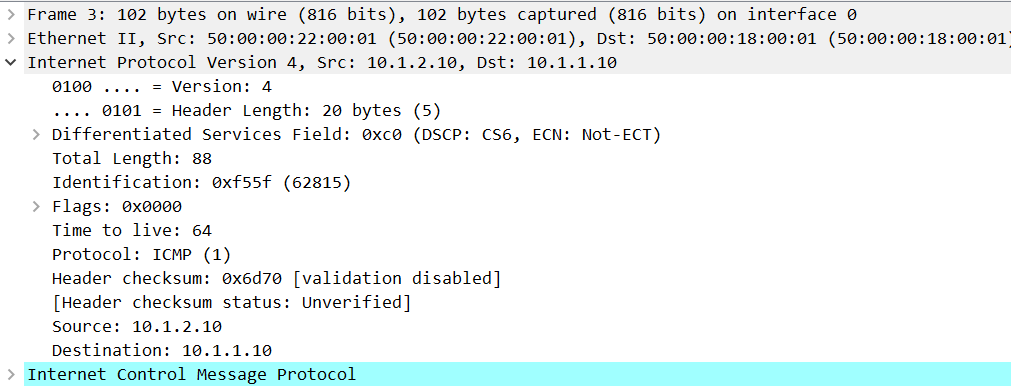
How did we find out that this was the FW and not 10.1.2.10 itself? As I mentioned before, we looked at a capture and this is the TTL when 10.1.2.10 sends IP packets:

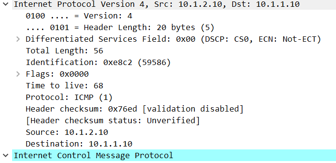
Now look at the packet that the FW sent to 10.1.1.10:

This packet was received with a TTL of 68 but B3-S1 sent its packet with a TTL of 64. This is simply impossible, unless we have a flux capacitor…
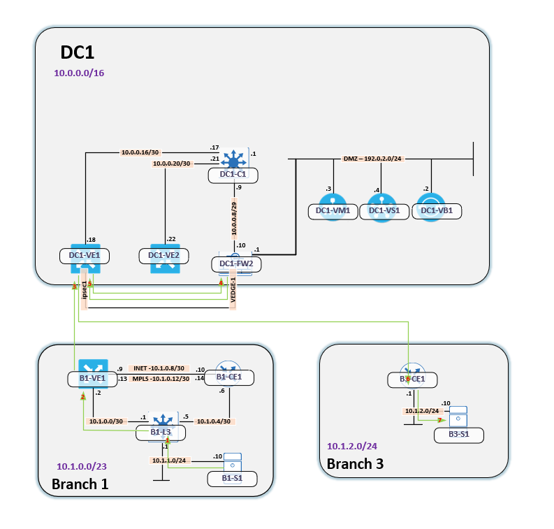
Why are we then seeing 10.0.0.18 twice in the traceroute? At first I thought this might be some kind of loop where traffic arrived at 10.1.2.10 and then the trace continued back along the reverse path. This was not the case however. The diagram below will show the flow of traffic:

The number in red indicates what hop it is in the traceroute. The path goes as follows:
- Traffic arrives at B1-L3
- Traffic then arrives at B1-VE1
- Then it goes to DC1-VE1
- Now it goes to DC1-FW
- It is now returned to DC1-VE1
- It then arrives at B3-CE1
- Finally it arrives at B3-S1
The key to understanding this traceroute is that traffic is hairpinned through the firewall and that the two hops with 10.0.0.18 is DC1-VE1, even though that interface is not really used in the data plane of this flow.
With this long post coming to an end, what have we learned?
- Traceroute most often uses UDP or ICMP
- Which one it uses, will have implications on filtering of traffic
- A traceroute may not always show exactly what is going on in the data plane
- Devices may source ICMP packets from interfaces we don’t expect
- Firewalls do firewall things… Such as ehm faking the source IP of ICMP packets
- Firewalls don’t like asymmetric traffic
I hope I have highlighted some interesting things in this post. It was a great learning experience for me personally. If you are interested in following along in my tweet, you can find it here:
Excellent post Daniel.
Maybe using tcptraceroute would have help reduce time required for troubleshooting.
Such good helpful information is given keep sharing more thanks for it