In the previous three parts, we learned about all the interesting things that go on in the PHY with scrambling, descrambling, synchronization, auto negotiation, FEC encoding, and so on. This is all essential knowledge that we need to have to understand how the PHY can detect that a link has gone down, or is performing so badly that it doesn’t make sense to keep the link up.
What Does IEEE 802.3 1000BASE-T Say?
The function in 1000BASE-T that is responsible for monitoring the status of the link is called link monitor and is defined in 40.4.2.5. The standard does not define much on what goes on in link monitor, though. Below is an excerpt from the standard:
Link Monitor determines the status of the underlying receive channel and communicates it via the variable
link_status. Failure of the underlying receive channel typically causes the PMA’s clients to suspend normal
operation.
The Link Monitor function shall comply with the state diagram of Figure 40–17.
The state diagram (redrawn by me) is shown below:
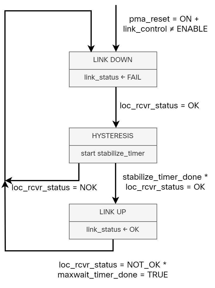
While 1000BASE-T leaves what the PHY monitors in link monitor to the implementer, there are still some interesting variables and timers that you should be aware of:
loc_rcvr_status – This is a variable set by the PMA Receive function. It indicates if the receive link for the local PHY is operating reliably or not.
rem_rcvr_status – This is a variable set by the PCS Receive function. It indicates if the receive link for the remote PHY is operating reliably or not.
scr_status – This indicates if the descrambler has achieved synchronization or not.
maxwait_timer – This timer is used to limit the time a receiver is in SLAVE SILENT and TRAINING state. The timer expires 750ms ± 10ms if config = MASTER or 350ms ± 5ms if config = SLAVE.
minwait_timer – This timer determines the minimum amount of time the PHY Control stays in the TRAINING, SEND IDLE, or DATA states. The timer shall expire 1 μs ± 0.1μs after being started.
The reason I bring this up is that there is some confusion around the maxwait_timer. I’ve seen people say that it takes up to 760ms to bring a link down, referencing this timer. This is however not correct. The maxwait timer is only relevant when the PHY is in the training and synchronization state, which occurs before bringing a link up. If you recall, in a previous post I described that equalizers and noise cancellers need to be trained before bringing a link up. The minwait timer defines the minimum amount of time to stay in the training phase and the maxwait timer the maximum amount of time to stay in the training phase. This means that maxwait is how long to wait before deeming the training as unsuccessful and preventing the link from being brought up. Figure 40-16a (redrawn by me), shows the different phases and their associated variables (I have highlighted the maxwait timer):
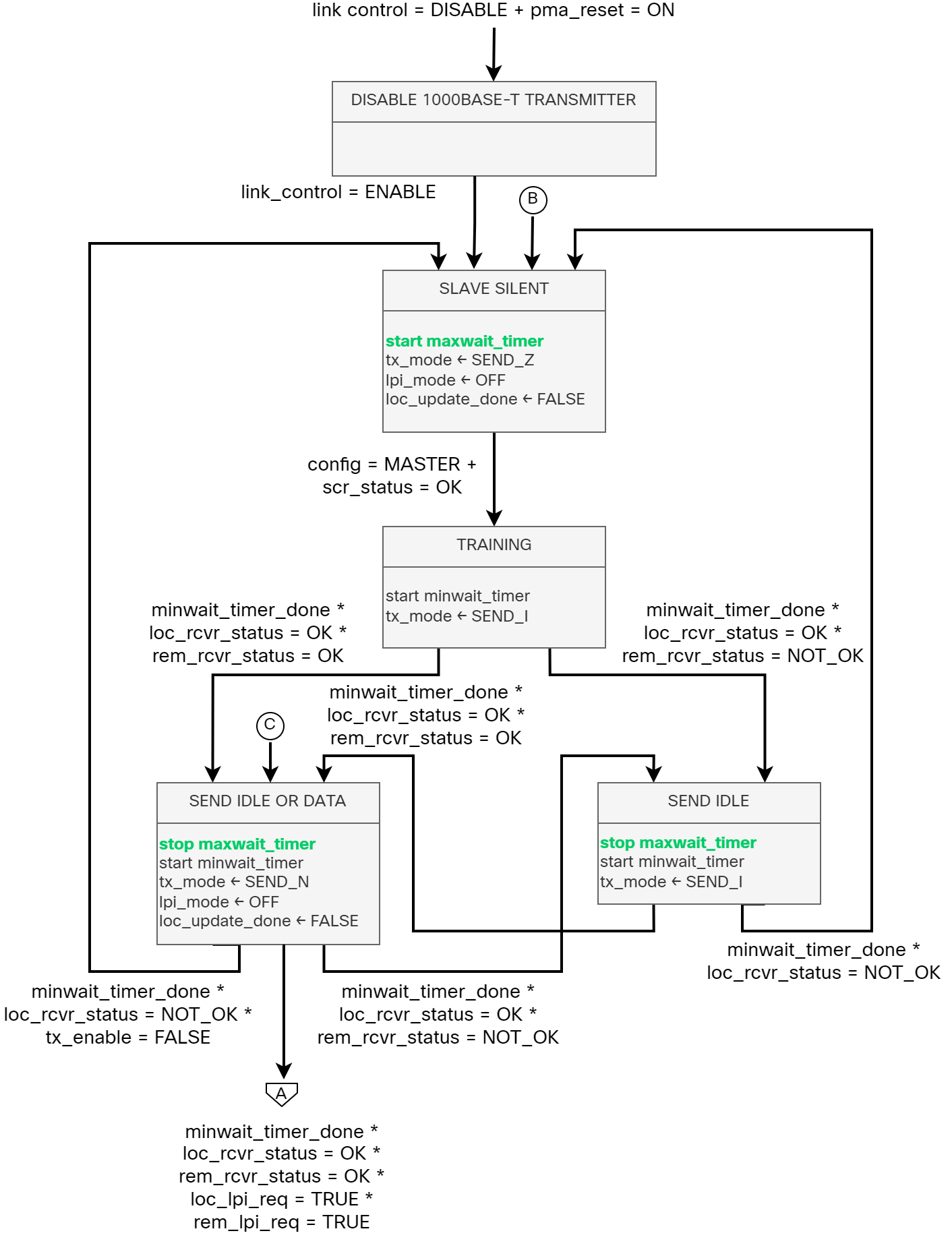
After training, the PHY will either send data and idle, or idle, and the maxwait timer is then stopped. Only if training is re-entered does the maxwait timer start again. Only if the training failed, the maxwait timer would expire, and in that case the link would not come up.
Noise Environment
Most of us in traditional networking roles don’t spend a lot of time considering how electrical and magnetic signals can affect the transmission of Ethernet frames. We know what cables to use, to not span them further than 100m, and so on, but generally don’t give it more thought than that. If you’ve read my previous posts, you’ll know how much goes on to be able to send Ethernet frames on one side and receive them on the other side. From a physical perspective, there are many things to consider such as:
- Insertion loss.
- Propagation delay.
- Characteristic impedance.
- NEXT loss.
- ELFEXT loss.
- Return loss.
In addition to these, which are controlled by the cable, there are external sources of noise from the environment. Deploying Ethernet in an industrial environment, for example, may have an effect on the noise levels. Something like an arc welder, AC, or even a vacuum machine will affect the signal. Let’s take a closer look at some of the factors for the noise environment in 1000BASE-T:
Echo – 1000BASE-T uses a hybrid approach where both transmit and receive is done on the same pair. Due to the bidirectional transmission, this creates echos. It would be impractical to achieve the Bit Error Rate (BER) defined for 1000BASE-T without performing echo cancellation. Thankfully, the symbols transmitted by the local transmitter are known, which means the echo interference can be reduced to a small residual noise.
NEXT – Near End Cross Talk (NEXT) is the interference from the three adjacent transmitters. To minimize the impact, NEXT cancelers are used. Once again, the symbols transmitted are known, which means the interference can be reduced. NEXT cancelers are used and can reduce NEXT interference by at least 20 dB.
FEXT – Far End Cross TALK (FEXT) is the interference from the three remote transmitters. FEXT noise is canceled in a similar fashion to echo and NEXT, but the symbols transmitted are not immediately known as they are coming from the remote side. FEXT noise is much lower than NEXT and can generally be tolerated.
ISI – Inter Symbol Interference (ISI) is extraneous energy from one signaling symbol interfering with the reception of another symbol on the same channel.
Noise from non-idealities in the duplex channel, transmitter, and receivers – It’s not possible to create a perfect transmitter. There will always be some non-idealities such as DAC/ADC non-linearity, electrical noise (shot and thermal), and non-linear channel characteristics.
Noise from sources outside the cable – As mentioned previously, sources outside the cable may couple into the link segment via electric or magnetic fields.
Alien NEXT – This is noise that is present when cables are bound tightly together. The symbols transmitted by the alien NEXT source is not available to the cancellation processor, making it difficult to cancel it.
As an added bonus, did you know that the length of the cable may vary slightly depending on temperature? Hence affecting propagation delay.
Now, why is all of this important? It’s important to understand these concepts to understand how a receiver can evaluate if it’s receiving valid symbols or not and when it’s time to bring a link down.
What Affects Bringing a Link Down?
As mentioned previously, what factors are involved in bringing a link down is left to the implementer and is not defined in the standard. This means that it will vary per PHY and also vary per the expected use of the PHY. In some environments it’s important to keep the link up a bit longer, even when seeing errors, while in other environments it may be desirable to bring the link down much faster. Keep in mind that Ethernet is used everywhere, from enterprises, to the automotive industry, to industry, and even space. You can imagine that based on your use case, you’ll have different requirements.
Let’s take a look at some of the metrics that are used to bring a link down. Remember, though that the exact mechanism used is dependent on the particular PHY design; however, there are a lot of metrics which are available internally to most designers. We will move from the lowest level and upwards, meaning that something like the Frame Check Sequence (FCS) comes last as there are already a lot of other checks performed before the FCS.
Energy detect – There is no signal detected. It’s not possible to infer any symbols at all as there is no voltage applied to the channel.
MSE – Mean Square Errors (MSE) is similar to SNR, but it also takes into account distortion and interference in addition to noise power. MSE measures the average of the squares of the errors. Just as with SNR, there are thresholds for what is acceptable on a link. The slicer component in PMA selects the PAM-5 symbol value (+2, +1, 0, -1, -2) after the symbol has been corrected for ISI, attenuation, echo, crosstalk, and Baseline Wander (BLW). The slicer produces an error output and symbol value decision.
Trellis encoding/Viterbi decoding – 1000BASE-T uses FEC in form of Trellis encoding and Viterbi decoding. If there is low confidence in the decoding process, this can also be taken into account.
Descrambler lock loss – If the descrambler loses its lock a number of times (it can recover the lock), then it can lead to bringing the link down.
FCS – FCS is performed via a Cyclic Redundancy Check (CRC). This is essentially a checksum that is calculated and if the calculation provides another checksum than was included in the frame, something happened to the frame. If there are too many errors, the link is not reliable and should be brought down. Unlike the other measures here, the FCS occurs not in the physical layer, but in the MAC. If a link needs to be brought down for too many frames with a bad FCS, a managed system may choose to reset the PHY and bring the link down.
As you can see, there are many factors here beyond the more obvious ones like energy detect.
How Long Does it Take?
How long does it then take before the link goes down? Once again, this is up to the implementer, but we can make some general claims. As you learned in previous posts, there is always something sent on the wire, be it data or IDLE. This occurs every 8 nano seconds. This means that we quickly acquire a lot of data. For example, let’s say we want to measure at least 100 symbols. That would be 800 nano seconds which is still less than a micro second. In some papers describing specific PHYs, I’ve seen 10 micro seconds mentioned as a number for fast link drop, which is faster than what you would generally see. Still, 10 micro seconds would provide us with 1250 symbols of data, which should be enough to make an informed decision. Keep in mind that for faster PHYs like 10 Gbit/s, 40 Gbit/s, 100 Gbit/s, and so on, symbols are sent at an incredibly fast rate providing a lot of symbols to base the decision on.
As I mentioned previously in the post, there is a confusion around what the maxwait timer is actually used for. It is used when the PHY is in the training phase. It does not take 760ms to bring a link down. A realistic expectation is that it could take no more than 1ms. Remember, 1ms of data would be 125000 symbols. That’s a lot of data!
This is one of the reasons why physical design is important in network design. Whether you run regular keepalives or BFD, there is nothing that can compete with the PHY detecting a link going down. Therefore, you should always strive for having end to end signaling where there are no intermediate devices or converters between the two PHYs that you want to monitor. This is not always possible, of course, such as when connecting an ISP to a switch where you have several devices that need to connect towards it, but it will have an impact on your HA design.
Summary
There’s a lot more going on in the physical layer than we generally think about. Which is the reason why it makes it difficult to answer the seemingly easy question I asked in the beginning, how does Ethernet detect link down? To my surprise, there was almost no online literature covering this at any depth. Thanks to my discussions with George Zimmerman and Peter Jones, we now have a much better answer of what actually goes on in the PHY and how Ethernet can detect link down. I hope this has been informative for you!
Hi Daniel,
Really nice series on 1000BASE-T so far! Do you have any takeaways of insights on this topic that you would apply in your regular work?
Thanks, Robert!
It has given me a better general understanding of the physical layer. Not something that is relevant in my day to day, but on higher speed interfaces, things like FEC are very relevant.
@Daniel Thank you for such a deep insight into the functionality of the 1000Base-T series. It was a great read!
Thank you!