Introduction
This post will discuss different design options for deploying firewalls and Intrusion Prevention Systems (IPS) and how firewalls can be used in the data center.
Firewall Designs
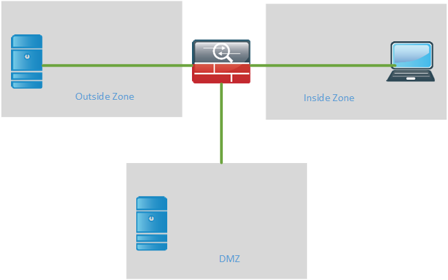
Firewalls have traditionally been used to protect inside resources from being accessed from the outside. The firewall is then deployed at the edge of the network. The security zones are then referred to as “outside” and “inside” or “untrusted” and “trusted”.

Anything coming from the outside is by default blocked unless the connection initiated from the inside. Anything from the inside going out is allowed by default. The default behavior can of course be modified with access-lists.
It is also common to use a Demilitarized Zone (DMZ) when publishing external services such as e-mail, web and DNS. The goal of the DMZ is to separate the servers hosting these external services from the inside LAN to lower the risk of having a breach on the inside. From the outside only the ports that the service is using will be allowed in to the DMZ such as port 80, 443, 53 and so on. From the DMZ only a very limited set of traffic will be allowed to the inside such as a frontend server accessing a service on the backend server.
Some organizations may use two firewalls between the outside and the inside. The benefit of this is debatable but the reasoning is that if one firewall is compromised, there is another one to breach before reaching the inside. For this reason it would be common to use to different vendors of the firewalls. That would likely keep the firewalls from having the same software bugs and/or exploits.

When using two firewalls, where do you place the DMZ? The DMZ could be placed at the first firewall.

There are some drawbacks to this design. If using two firewalls, why only send the incoming traffic to the DMZ through the first one? Any traffic from the inside to the DMZ will also have to pass two firewalls and those rules are probably more complex than the rules allowing traffic from the outside to the DMZ which may become an administrative burden.
The next option is to put the DMZ behind the second firewall.
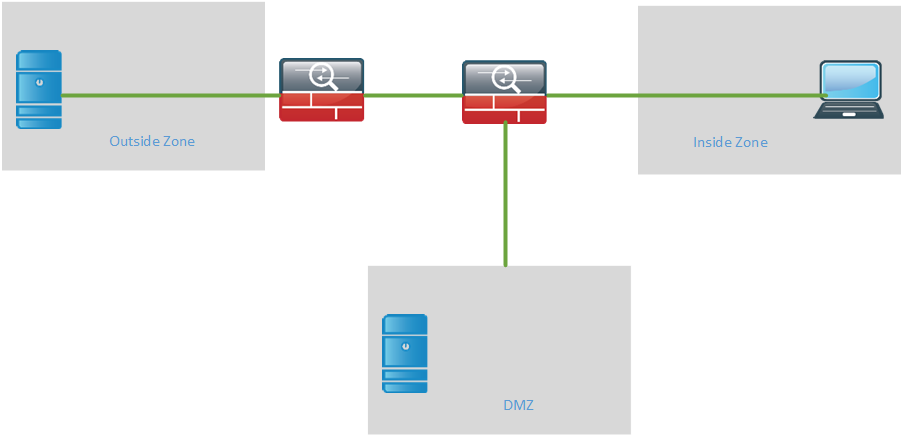
The advantage of this design is that external traffic to the DMZ must pass through both of the firewalls. Internal traffic to the DMZ only has to pass through one firewall which lessens the administrative burden of this ruleset.
There are also tiered firewall designs which are common in e-commerce solutions. Every tier is a security zone and servers are placed in the different tiers. The most common example is where the web server communicates with the application server but not the database server directly. The application server communicates with the database server. Each tier then has its own firewall.
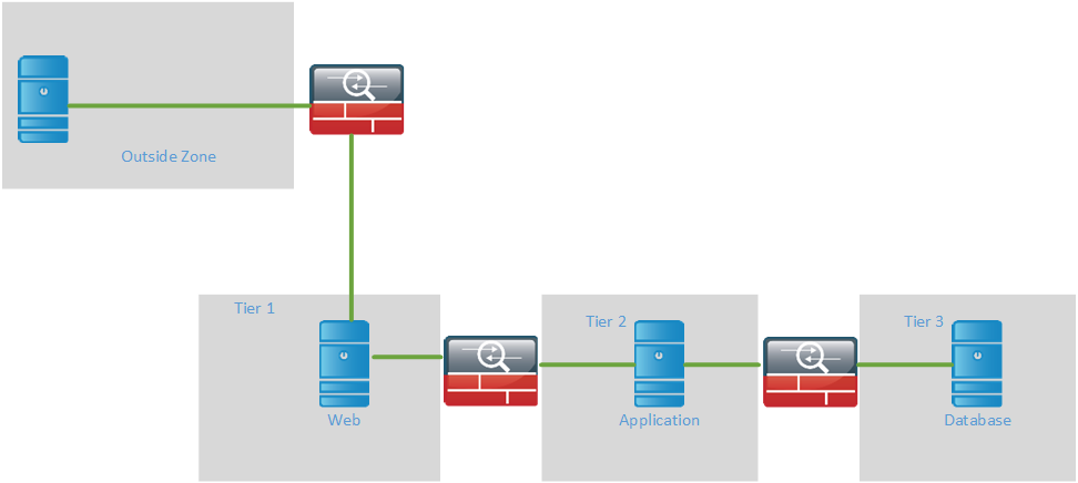
In this design traffic flows through each zone and only certain traffic is allowed to pass between the zones. In older designs it was common to use physical firewalls, that’s all that was available. In newer designs it is common to use contexts or equivalent virtualization techniques from other vendors. With contexts, a single physical firewall can be divided into multiple logical ones which behaves like a separate firewall. Each firewall is managed by itself and behaves like a normal firewall. Interfaces have to be assigned to the logical context from the system context. The context share the same physical resource which can lead to a situation where one context can starve the others for CPU and memory. Each context can be assigned a share of the resources to prevent this from happening. Keep in mind that some features may not be available in a context such as remote access VPN and site to site VPN.
Routed Or Transparent Mode?
Firewalls can be run in routed mode or transparent mode where routed mode is by far the most common. Routed mode is the traditional mode of the firewall where two or more interfaces separate L3 domains. Transparent mode is where the firewall acts as a bridge functioning mostly at L2.
The transparent firewall provides an option in traditional L3 environments where existing services can’t be sent through the firewall. This mode is very popular in data center environments. The transparent firewall has the following characteristics:
- Routing protocols can establish adjacencies through the firewall
- Protocols such as HSRP, VRRP, GLBP can pass
- Multicast streams can traverse the firewall
- Non IP traffic can be allowed through such as IPX, MPLS and BPDUs
- Allows for three zones such as inside, outside and DMZ
- No dynamic routing protocol support or VPN support
The main advantage of the transparent firewall is that it allows for more flexible routing designs since the firewall does not have to be part of the routing domain. Firewalls may not always support the same protocols as the other network devices, leading to static routes and redistribution between different routing domains. Another advantage is that multicast may be passed through transparently as opposed to the often limited multicast capabilities of firewalls to act as PIM routers.

What may seem confusing is that the same IP subnet is used on both sides but on different VLANs, this is different from the normal one VLAN equals one subnet design. The firewall will have a Bridged Virtual Interface (BVI) for management which also resides in the same IP subnet.
The transparent firewall can transparently be inserted into the L3 domain.

Firewalls in transparent mode do not do NAT, which is another design consideration when running the firewall in transparent mode.
IPS and IDS
IPS is a device that is used to prevent attacks on the infrastructure. This is normally done based on signatures. A firewall may only inspect that traffic is coming in on the correct port but what if that traffic is malicious? The IPS can update its signatures to find new exploits that have been seen in the wild. This is done by subscribing to the updates.
When an IPS is run in inline mode, it is called IPS because it can prevent attacks. All the traffic passes through the IPS.
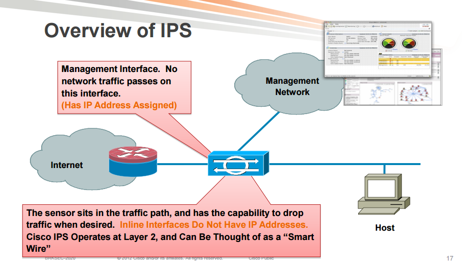
When an IPS is run in promiscous mode it does not sit inline with the traffic, it receives a copy of the traffic. The IPS is then referred to as an IDS because it detects attacks but does not actively prevent them as it does not sit in the traffic flow.
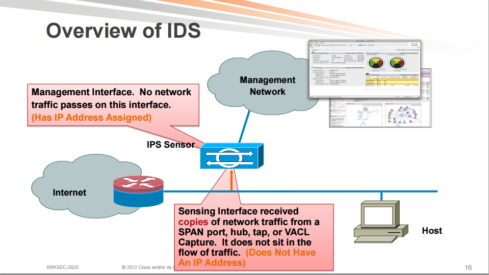
There are different design considerations for an IPS in inline mode or promiscous mode.
IPS inline mode:
- Can stop an attack by dropping packets
- Can normalize traffic before sending it further into the network
- Overloading the sensor will affect the network traffic
- Failure of the device will affect the network traffic
IPS promiscous mode:
- No impact on the network, no added latency or jitter
- False positives have less affect than in inline mode
- Limited protection
- More vulnerable to evasion
An IPS in inline mode can perform different actions on the flow.
Deny attacker inline: Blocks all traffic from the attacking host through the IPS for a specified period of time. This is the most severe action and should be used when the probability of false alarms or spoofing is minimal.
Deny attacker service pair inline: This action prevents communication from the attacking host to the protected network on a specific port. This works well for worms that infect hosts on the same port. The attacker is able to communicate on another port on the protected network. Also this mode should be used when the likelihood of a false alarm or spoofing is minimal.
Deny attacker victim pair inline: Prevents the attacker from communicating with the victim on any port. The attacker can communicate with other hosts. Suitable for attacks that are targeted for a specific host. Use this mode when the likelihood of a false alarm or spoofing is minimal.
Deny connection inline: This action prevents further communication for the specific TCP flow. This mode is suitable if the administrator wants to prevent the action but not deny further communication. This mode is suitable when there is potential for a false alarm or spoofing.
Deny packet inline: Prevents the specific offending packet from reaching its intended destination. Other communication between the attacker and the victim may still exist. This mode is suitable when there is the potential for a false alarm or spoofing.
Modify packet inline: Enables the IDS device to modify the offending part of the packet and then forwards the packet to its destination. This is appropriate for packet normalization and other anomalies, such as TCP segmentation and IP fragmentation reordering.
When the IPS is not placed in inline mode, it can’t directly take action since it is acting on the original flow, merely a copy of the traffic. The IPS can only request other devices to take action on the flow through an Attack Response Controller (ARC) request. The following are some actions that can be requested.
Request block host: This event action will send an ARC request to block the host for a specified time frame, preventing any further communication. This is a severe action that should be used when there is a minimal chance of false alarms or spoofing.
Request block connection: Will send an ARC request to block the specific connection. This action is appropriate when there is potential for false alarms or spoofing.
Reset TCP connection: Resets the TCP session, can be successful if the attack requires several TCP packets but not for attacks only requiring one packet. It’s also not effective for protocols such as SMTP that consistently try to establish new connections.
When an IPS is deployed in inline mode, there’s always the risk of the device failing which would effectively stop all the traffic from passing. There are bypass features that can be deployed, both hardware based and software based so that traffic can pass through the IPS if it fails. For some organizations it may be a requirement for all traffic to pass through an IPS though, which would lead to a redundant IPS pair.
Placement Of IPS
Should the IPS be deployed in front or behind the VPN concentrator or firewall?

The VPN traffic should be decrypted first so that the IPS can look into the payload (layer 7) for malicious traffic.
Should the IPS be deployed before or after the firewall?

If the IPS is deployed before the firewall it gives somewhat better visibility into attacks/threats from the Internet. On the other hand the IPS will have to handle more traffic/state and may become a chokepoint. The IPS can also be deployed after the firewall which is the most common.

With the IPS behind the firewall it does not have to deal with common attacks such as SQL slammer, worms carried by NetBIOS and simple script kiddy scanning.
If the IPS appliance is inspecting clientless SSL VPN traffic, be aware that visibility is lost as the individual source/destination pair is not visible. An action like drop attacker is not recommended since it would block all the traffic behind the proxy.

The most important thing to remember with an IPS is that it is not a plug and forget system. It requires a lot of tuning and continiously reviewing the security policy and the number of false alarms.
Firewalls In The Data Center
A standard topology in the data center may look something like the topology below.
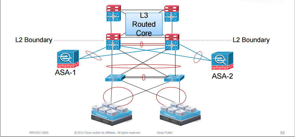
The firewalls are redundantly connected to typically Nexus switches running vPC. Firewalls can be deployed in either active/standby mode or active/active mode.
A common design in the data center is to run the firewall in transparent mode. The gateway is then placed outside of the firewall and the firewall is L2 adjacent with the hosts. Clients are segmented through VLANs.

Another design is to use VDCs on the Nexus and place a firewall that inspects intra-VDC traffic. Segmentation is done through VRFs on the Cat6500 or Nexus.

The firewall can be in either L2 (transparent) or L3 (routed) mode. The server gateway is inside of the firewall.
Firewalls can also be used to inspect inter-VDC traffic and the firewall is then sandwiched between the VDCs.
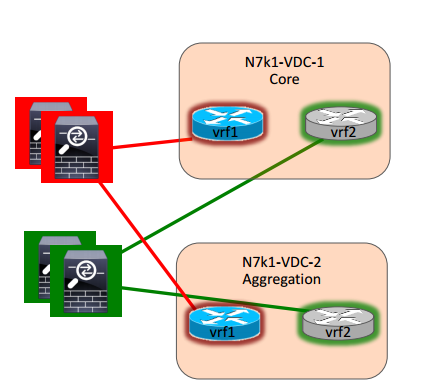
The firewall can be in L2 or L3 mode. Other services such as IPS and load balancing can be layered in as needed as well. The firewalls could be virtualized through contexts to provide a 1:1 mapping to VRFs. This design is useful when a FW is required between aggregation and core. The downside to this design is that all traffic passes the FW which could become a bottleneck.
Traditional firewalls are good with North-South flows, meaning traffic that flows to and from access layer to aggregation layer and core. East-West flows is typically server to server traffic often stays within the same zone or between zones.
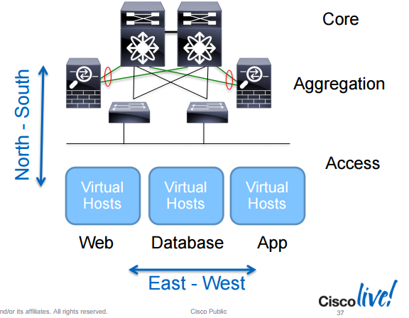
To better deal with East-West traffic, the Virtual Security Gateway (VSG) is a Cisco product which runs as a VM and can inspect traffic within a subnet or VLAN.
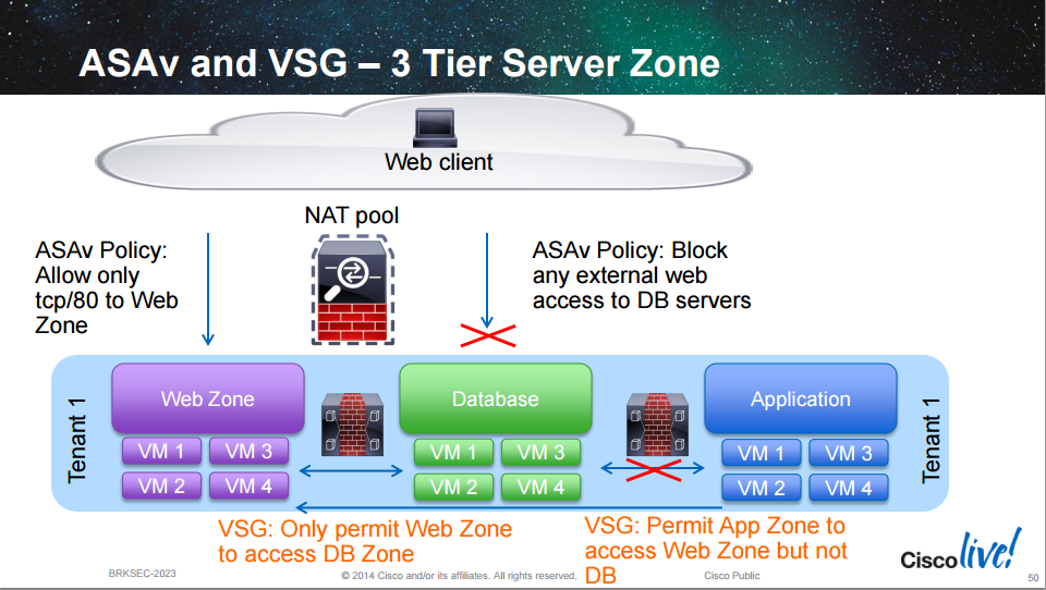
The VSG has the following characteristics:
- L2 firewall that runs as a virtual machine “bump in the wire”
- Similar to the transparent mode of the ASA
- It provides stateful inspection between L2 adjacent hosts (same subnet or VLAN)
- It can use VmWare attributes for policy
- Provides L2 separation for East-West traffic flows
- One or more VSGs deployed per tenant
With the VSG it’s easier to create policy for tiered applications which may reside in the same subnet such as e-commerce solutions.
The next topology shows an advanced design which uses VDCs and firewalls in both transparent and routed mode for different requirements.
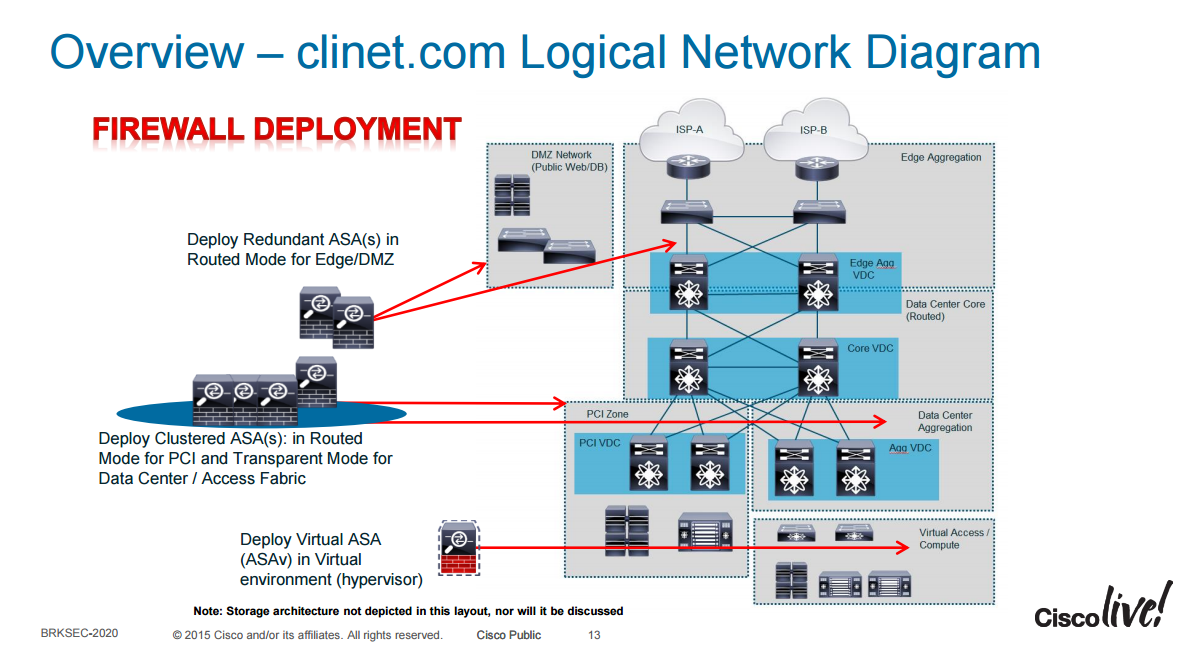
Nexus switches are used and through VDCs they are divided logically into three functions, “Edge Agg”, “Core” and “Agg”. Firewalls at the edge are deployed in routed mode to be able to do VPNs and NAT if required. There is also a PCI VDC for services that require PCI compliance. Firewalls in the PCI zone are deployed as routed firewalls while the firewalls in the Agg zone are deployed as transparent firewalls.
Clustering
A new design is to use clustering of firewalls. All the firewalls act as one logical firewall.
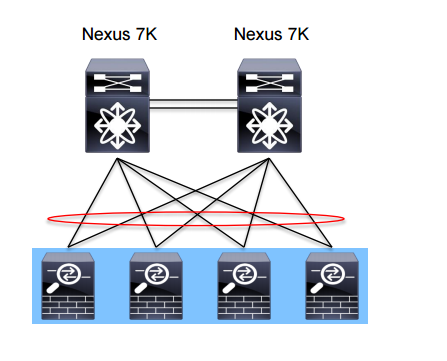
The benefit of clustering is that it’s easy to add capacity. If one firewall can do 5 Gbit/s of forwarding, adding a second one does not give you 10 Gbit/s but approximately 70% of the forwarding capacity so 7 Gbit/s while only managing one unit. It also supports asymmetric traffic flows which is very beneficial for a firewall which does normallly not handle asymmetric traffic flows well. It also provides redundancy, any traffic flow will have N + 1 redundancy with a backup firewall for every active flow. Configuration is synchronized between the firewalls so only one device needs to be configured.
Internet Edge Design
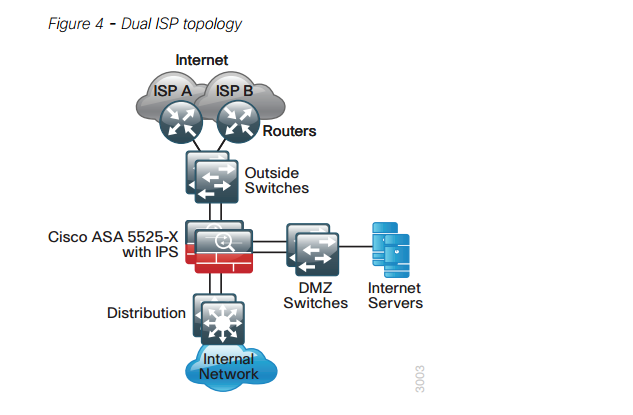
The following diagram shows a common Internet Edge design from the Cisco Validated Design (CVD) guide.
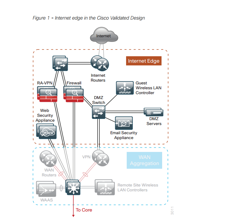
Routers are used at the edge for routing and peering with service providers. Switches are connected to these routers so that the VPN concentrator and firewall can connect to the outside network. There is also a DMZ switch for the DMZ zone which hosts services that should be accessed from the outside.
There is also a WAN aggregation zone where WAN routers and VPN routers reside. These routers connect for example to service provider MPLS VPN and/or DMVPN cloud. The WAN aggregation switches connect to the core.
The next diagram shows a more detailed view of the outside zone.
The edge routers connect to two service providers for redundancy. Internet servers are placed behind the DMZ switches.
This post should give you a basic introduction to firewalls and IPS and what modes they can be deployed in and where they are commonly placed in enterprise and data center designs. Good luck with your studies.
Well done Daniel.
Hence you talked about clustering, what do you think about clustering over DCI? And streched VLANs over DCI?
I’m not sure whether DCI is part of CCDE blueprint.
In another post I read that you talked about Load Balancers. Just as a suggestion, maybe you would like to write about the architecture where there are both Load Balancers and Proxies.
Kind Regards,
Mohammad Moghaddas
Hi Daniel and Mohammad!
Daniel, very nice blog post!!
Mohammad, I believe that these two posts can answer your question:
http://blog.ipspace.net/2011/04/distributed-firewalls-how-badly-do-you.html
http://blog.ipspace.net/2015/11/stretched-firewalls-across-layer-3-dci.html
Hope that Daniel agrees with Ivan 😀
Regards,
Augusto
Yes, Ivan is a very smart guy and I often agree with him 🙂 I don’t think it’s a good idea to stretch a firewall cluster across the data centers since you risk losing both of them if the DCI link goes down.
Hi Augusto,
Thank you for your comment.
To be honest, I’m already a fan of Ivan and have read those links. Just wanted to know the opinion of Daniel hence he’s also an experienced Architect and CCDE-to-be.
While writing this comment, I read that Daniel also agrees with Ivan.
Cheers.
Hello Daniel,
Nice post!
I have a case where we want to use 2 x fortigate firewalls in Active/active setup connected to nexus switches with vPC.
In case on ASA, for the ctrl different vPC domains are used for each FW while for the data a single vPC domain is used for all the FWs.
Do you have any experience how to do this with fortigate FW? should we use one or two vPC domains.
PS: No resources to lab it up at the moment
Daniel, I can read : “Firewalls in transparent mode do not do NAT”.
Be careful, since many Firewall can do NAT when being in transparent mode (like SLB do in Bridge mode…). I tested this with Fortigate…
Nice article BTW 🙂