Everyone knows that OSPF is a link state protocol. Those that study also discover that OSPF behaves like distance vector between areas as Type-1- and Type-2 LSAs are not flooded between areas, but rather summarized in Type-3 LSAs. This means that OSPF is a logical star, or hub with spokes, where Area 0 is the backbone and all other areas must connect to Area 0. This is shown below:
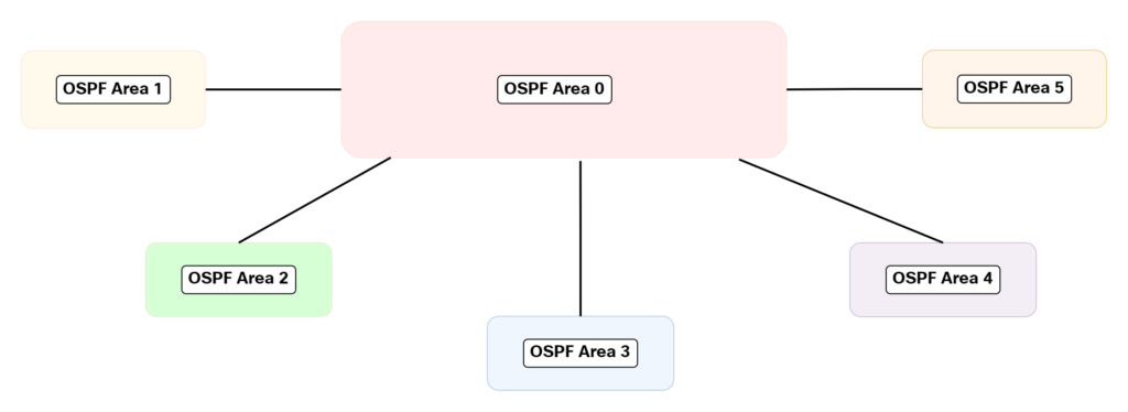
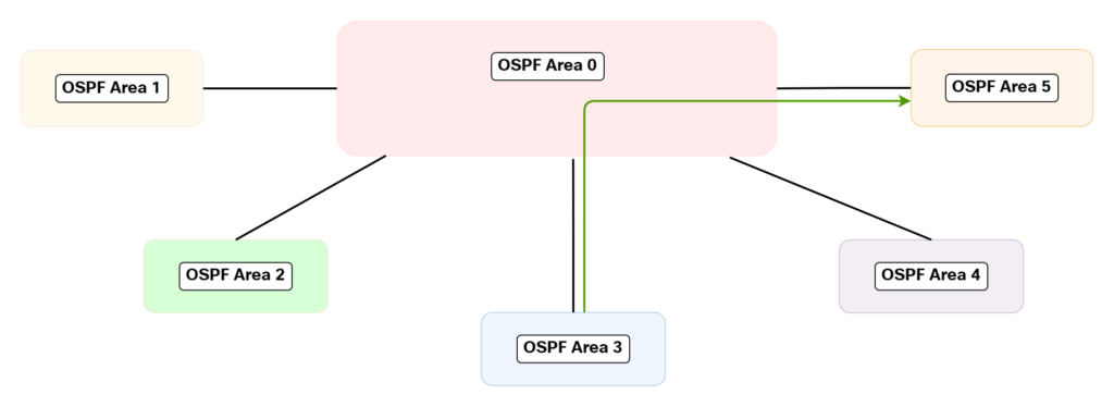
With this topology, since all the areas only connect to the backbone area, traffic between areas must traverse the backbone:
We learn about this behavior in literature where there is a very straight forward topology where each ABR is only attached to one area beyond the backbone. Such a topology is shown below:
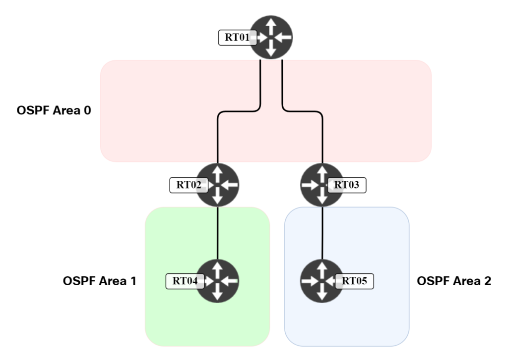
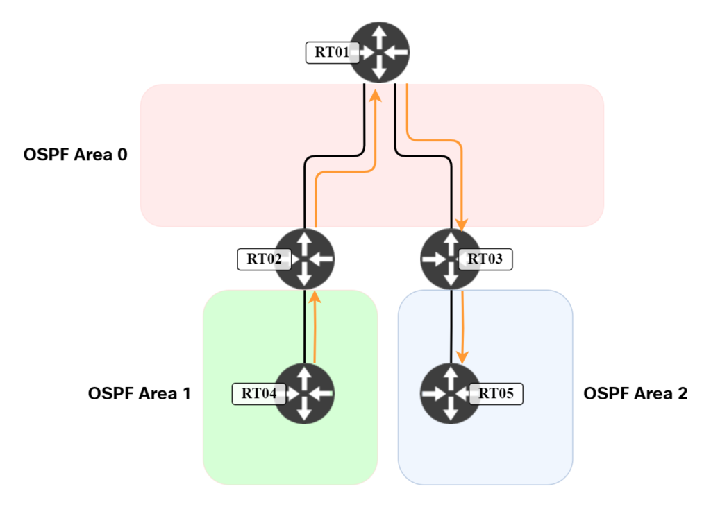
In such a topology, traffic between RT04 and RT05 has to traverse the backbone. This is shown below:
However, what if you have a topology which is not as clear cut? Where an ABR attaches to multiple areas? This is what we will explore in this post. We’ll be using the topology below:
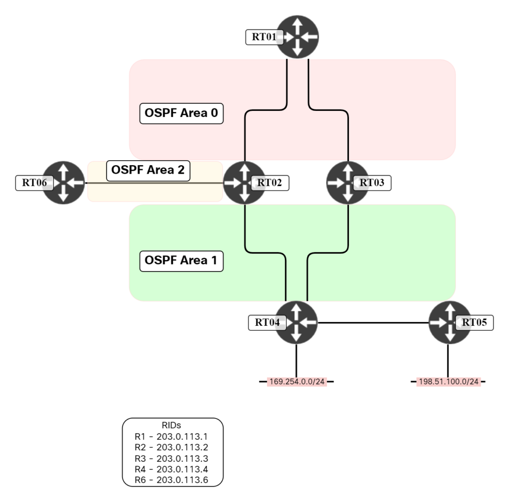
In this topology, RT02 and RT03 are ABRs. RT02 is attached to both Area 1 and Area 2 in addition to the backbone, while RT03 is only attached to Area 1. How will traffic flow in such a topology between Area 2 and Area 1? Most people assume that all traffic traverses the backbone like below:
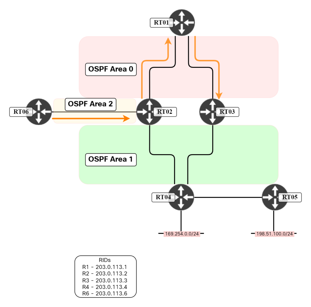
This is however not correct. Traffic will actually flow like this:
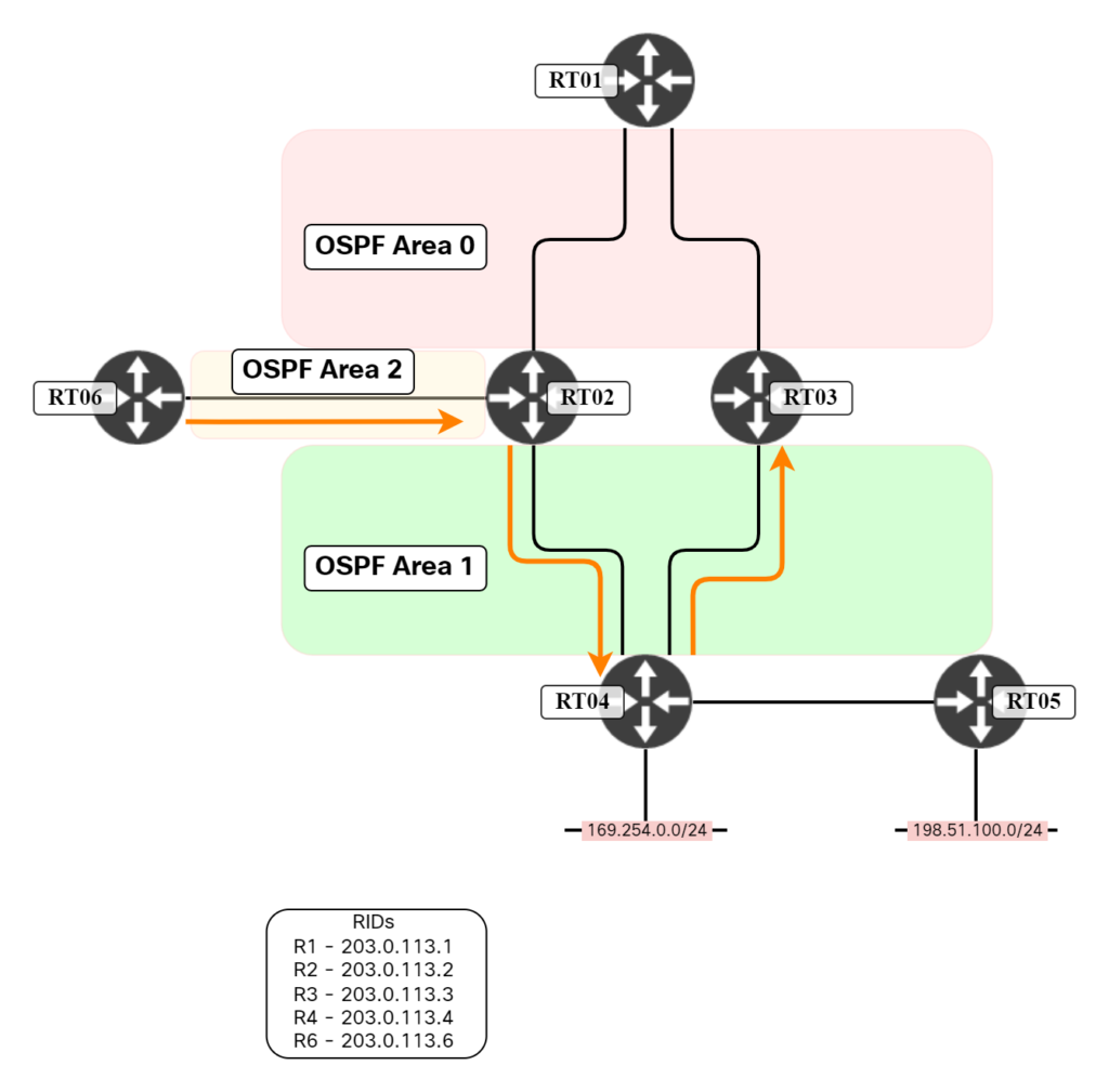
Why? To understand this, we need to review the LSDB and the LSAs. RT03 has an interface in Area 1 in the network 192.0.2.12/30. RT02 knows of this through the RT03 Router LSA:
R2#show ip ospf data router 203.0.113.3

                Router Link States (Area 1)

  LS age: 733
  Options: (No TOS-capability, DC)
  LS Type: Router Links
  Link State ID: 203.0.113.3
  Advertising Router: 203.0.113.3
  LS Seq Number: 800000FF
  Checksum: 0xC5FF
  Length: 48
  Area Border Router
  Number of Links: 2

    Link connected to: another Router (point-to-point)
     (Link ID) Neighboring Router ID: 203.0.113.4
     (Link Data) Router Interface address: 192.0.2.13
      Number of MTID metrics: 0
       TOS 0 Metrics: 1

    Link connected to: a Stub Network
     (Link ID) Network/subnet number: 192.0.2.12
     (Link Data) Network Mask: 255.255.255.252
      Number of MTID metrics: 0
       TOS 0 Metrics: 1
RT02 is going to generate two Type-3 LSAs, one for Area 0 and one for Area 2, summarizing this information that it learned from RT03:
R2#show ip ospf data summary self-originate

            OSPF Router with ID (203.0.113.2) (Process ID 1)

                Summary Net Link States (Area 0)

LS age: 1329
  Options: (No TOS-capability, DC, Upward)
  LS Type: Summary Links(Network)
  Link State ID: 192.0.2.12 (summary Network Number)
  Advertising Router: 203.0.113.2
  LS Seq Number: 800000FC
  Checksum: 0xEA49
  Length: 28
  Network Mask: /30
        MTID: 0         Metric: 2

                Summary Net Link States (Area 2)

LS age: 1329
  Options: (No TOS-capability, DC, Upward)
  LS Type: Summary Links(Network)
  Link State ID: 192.0.2.12 (summary Network Number)
  Advertising Router: 203.0.113.2
  LS Seq Number: 800000D7
  Checksum: 0x3524
  Length: 28
  Network Mask: /30
        MTID: 0         Metric: 2
RT06 has the LSA in its LSDB:
R6#show ip ospf data summary 192.0.2.12

            OSPF Router with ID (203.0.113.6) (Process ID 1)

                Summary Net Link States (Area 2)

  LS age: 1548
  Options: (No TOS-capability, DC, Upward)
  LS Type: Summary Links(Network)
  Link State ID: 192.0.2.12 (summary Network Number)
  Advertising Router: 203.0.113.2
  LS Seq Number: 800000D7
  Checksum: 0x3524
  Length: 28
  Network Mask: /30
        MTID: 0         Metric: 2
Hence it has installed an inter-area path for 192.0.2.12/30 via RT2:
R6#show ip route 192.0.2.12
Routing entry for 192.0.2.12/30
  Known via "ospf 1", distance 110, metric 3, type inter area
  Last update from 192.0.2.21 on GigabitEthernet0/0, 4d23h ago
  Routing Descriptor Blocks:
  * 192.0.2.21, from 203.0.113.2, 4d23h ago, via GigabitEthernet0/0
      Route metric is 3, traffic share count is 1
Let’s run a traceroute on RT06:
R6#traceroute 192.0.2.13 numeric
Type escape sequence to abort.
Tracing the route to 192.0.2.13
VRF info: (vrf in name/id, vrf out name/id)
  1 192.0.2.21 4 msec 6 msec 4 msec
  2 192.0.2.10 5 msec 5 msec 5 msec
  3 192.0.2.13 6 msec *  6 msec
The first hop is to RT02 which then sends it to RT04. Why RT04 and not RT01? RT02 has two paths to 192.0.2.12, the one via RT04 is intra-area and the one via RT01 (advertised by RT03) is inter-area:
R2#show ip ospf data summary 192.0.2.12 adv-router 203.0.113.3

            OSPF Router with ID (203.0.113.2) (Process ID 1)

                Summary Net Link States (Area 0)

  LS age: 607
  Options: (No TOS-capability, DC, Upward)
  LS Type: Summary Links(Network)
  Link State ID: 192.0.2.12 (summary Network Number)
  Advertising Router: 203.0.113.3
  LS Seq Number: 800000FD
  Checksum: 0xD85A
  Length: 28
  Network Mask: /30
        MTID: 0         Metric: 1
Intra-area always beats inter-area, regardless of metric, so traffic is kept within Area 1 without traversing Area 0.
It may be a bit confusing that RT02 is taking information from Area 1 and Area 2 and summarizing into Type-3 LSAs sent between the areas, but there is nothing in OSPF restricting this behavior. RT02, as it is attached both to the backbone area and other area(s) is by definition an ABR. An ABR is allowed to generate Type-3 LSAs. There is nothing saying that the ABR can’t generate Type-3 LSAs between non-backbone areas. There is some nuance here that I’ll get back to. First let’s do a traceroute on RT03 towards RT06:
R3#traceroute 192.0.2.22 numeric
Type escape sequence to abort.
Tracing the route to 192.0.2.22
VRF info: (vrf in name/id, vrf out name/id)
  1 192.0.2.5 10 msec 3 msec 4 msec
  2 192.0.2.2 8 msec 5 msec 7 msec
  3 192.0.2.22 9 msec *  5 msec
What’s interesting here is that traffic is flowing the other way around, through Area 0:
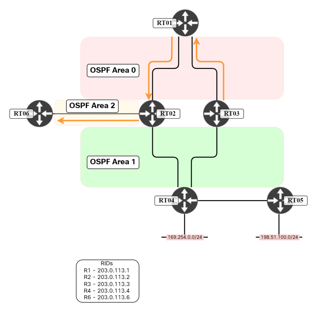
RT03 does not have an intra-area path towards RT06. It has a summary LSA in Area 1 from RT02:
R3#show ip ospf data summary 192.0.2.20

            OSPF Router with ID (203.0.113.3) (Process ID 1)

                Summary Net Link States (Area 1)

 LS age: 1339
  Options: (No TOS-capability, DC, Upward)
  LS Type: Summary Links(Network)
  Link State ID: 192.0.2.20 (summary Network Number)
  Advertising Router: 203.0.113.2
  LS Seq Number: 800000D8
  Checksum: 0xD878
  Length: 28
  Network Mask: /30
        MTID: 0         Metric: 1
However, RT03 can’t use this LSA because it’s an ABR and ABRs only process Type-3 LSAs originated from the backbone. Instead, it it using the LSA that came from the backbone:
R3# show ip ospf rib 192.0.2.20

            OSPF Router with ID (203.0.113.3) (Process ID 1)


                Base Topology (MTID 0)

OSPF local RIB
Codes: * - Best, > - Installed in global RIB
LSA: type/LSID/originator

*>  192.0.2.20/30, Inter, cost 3, area 0
     SPF Instance 18, age 5d00h
      contributing LSA: 3/192.0.2.20/203.0.113.2 (area 0)
     Flags: RIB, PartialSPF
      via 192.0.2.5, GigabitEthernet0/0 label 1048578
       Flags: RIB
       LSA: 3/192.0.2.20/203.0.113.2
In our scenario, traffic flows in different directions depending on where the flow is initiated. There is asymmetrical routing.
Now, coming back to RT06, what would happen with the traffic flow if we make it an ABR? Is it enough to add an interface to Area 0 to make it an ABR? Let’s try! First, let’s verify that it’s not currently an ABR:
R6#show ip ospf | i border
No match! Let’s add an interface to Area 0:
R6(config)#int gi0/1
R6(config-if)#ip ospf network point-to-point
R6(config-if)#ip add 192.0.2.26 255.255.255.252
R6(config-if)#no shut
R6(config-if)#ip ospf 1 area 0
Is it an ABR now?
R6#show ip ospf | i border
 It is an area border router
Yes, let’s now run a traceroute towards RT03 again:
R6#traceroute 192.0.2.13 numeric
Type escape sequence to abort.
Tracing the route to 192.0.2.13
VRF info: (vrf in name/id, vrf out name/id)
  1 192.0.2.21 10 msec 3 msec 4 msec
  2 192.0.2.10 5 msec 5 msec 5 msec
  3 192.0.2.13 7 msec *  8 msec
Nothing has changed so far. This is because RT06 doesn’t have a full adjacency in Area 0. I’ll now configure RT01 with an interface towards RT06 get an adjacency up in Area 0:
R1(config-if)#ip add 192.0.2.25 255.255.255.252
R1(config-if)#ip ospf network point-to-point
R1(config-if)#ip ospf 1 area 0
R1(config-if)#no shut
RT06 now has a full adjacency in Area 0:
%OSPF-5-ADJCHG: Process 1, Nbr 203.0.113.1 on GigabitEthernet0/1 from LOADING to FULL, Loading Done
Let’s run that traceroute again:
R6#traceroute 192.0.2.13 numeric
Type escape sequence to abort.
Tracing the route to 192.0.2.13
VRF info: (vrf in name/id, vrf out name/id)
  1 192.0.2.25 3 msec 3 msec 4 msec
  2 192.0.2.6 6 msec *  5 msec
Traffic is now flowing via RT01:
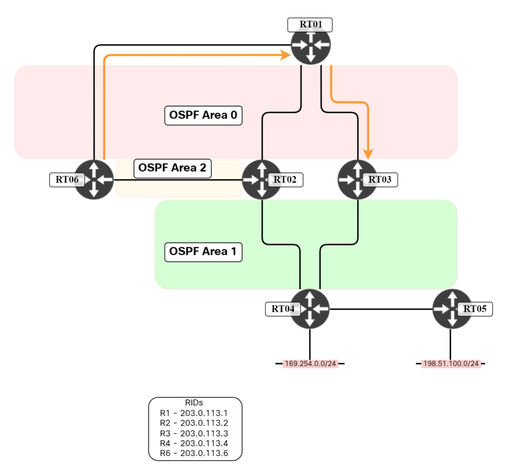
The reason for this is that as RT06 is now an ABR, it can no longer accept Summary LSAs coming into Area 2 from RT02. This is the distance vector loop prevention behavior of OSPF.
Summary
All areas must logically connect to the backbone area, Area 0. However, that doesn’t mean that all traffic between areas must flow via an interface that is in Area 0. There are scenarios where an ABR is attached to multiple areas where there is an intra-area path available once traffic hits the ABR. A router that is internal to an area, such as RT06 originally, will happily process Type-3 LSAs from a non-backbone area. As it’s not connected to the backbone, it’s safe to do so, and it’s the only available path. As soon as a router becomes an ABR, and has a full adjacency in Area 0, it will no longer process Type-3 LSAs that come in from non-backbone areas.
I hope this post has given you some insight into the behavior of OSPF and busted some common myths.
Thanks Daniel for this article.
I have learnt a lot. Pls keep them coming