A while back I started thinking about why it took so long before we started using anycast gateways. I started thinking about what would be the reason(s) for not doing it earlier. I came up with some good reasons and it started making sense to me. I then asked you all what your thoughts were and received a ton of great responses. Here are a few that were mentioned:
- It was a natural evolution.
- More powerful devices.
- We didn’t have overlays.
- There were no protocols to map what device a MAC sits behind.
- Reusing the same IP would cause IP conflicts.
These are all certainly true to some degree. I would argue though that the main reason why we didn’t have it earlier is because of the topology and protocols we used in traditional LANs. The typical design was to have three layers, access, distribution, and core. The links in access to distribution layer were L2 only and the distribution layer had all the L3 configuration. A typical topology looked like this:
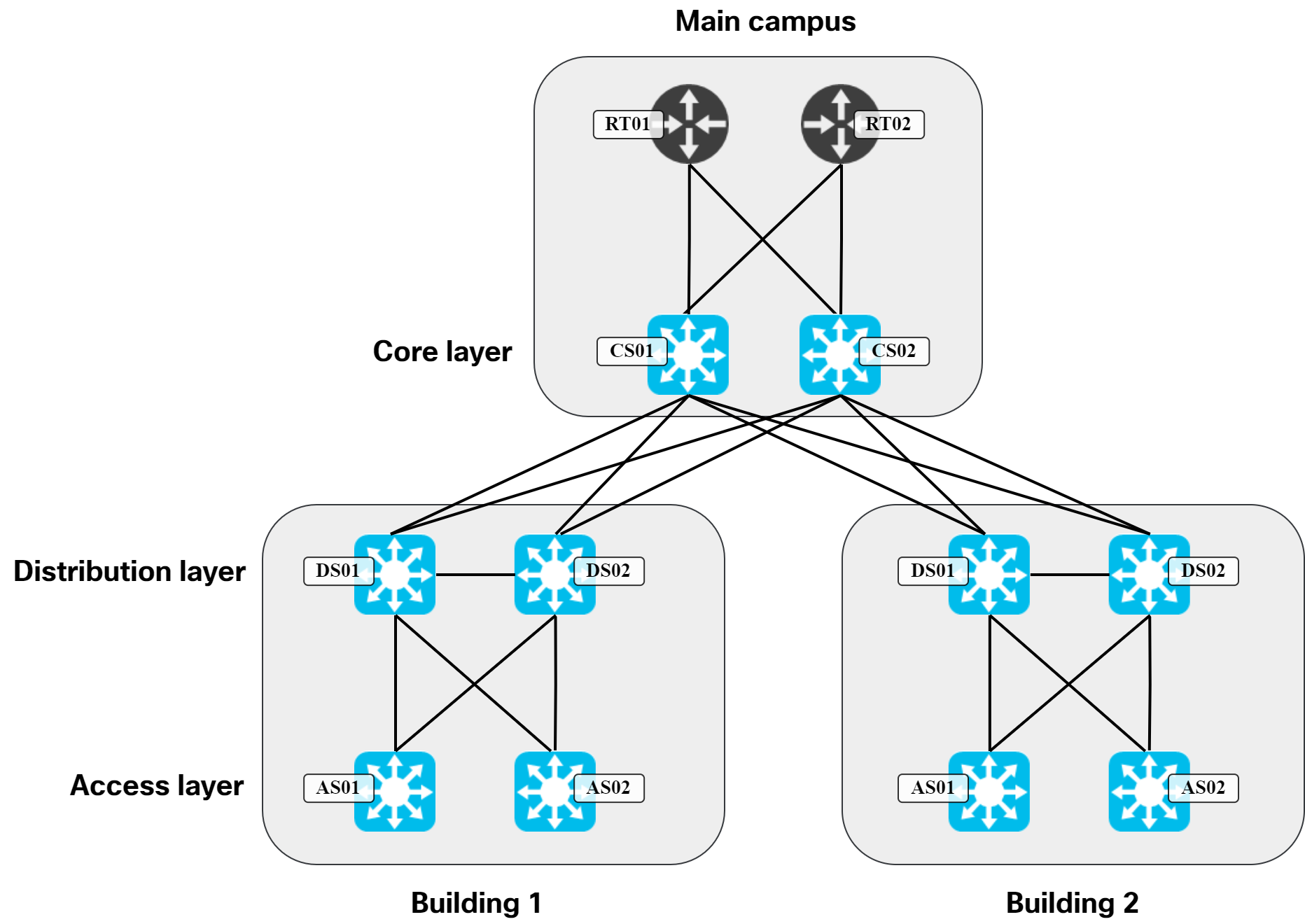
In a topology like this, there are only two devices that host the L3 configuration needed for hosts. When you have two of something, it’s natural to think in terms of primary and secondary, or active and standby. This is where protocols like HSRP and VRRP came to fruition. Could we use more than two devices in the distribution layer? Sure, but it would come with a lot of challenges:
- With STP, only one link is going to be forwarding.
- Having more than two distribution switches would be cost prohibitive.
- It would be a challenge, both from physical- and cost perspective, to get all the fiber needed.
- It would seriously complicate the topology.
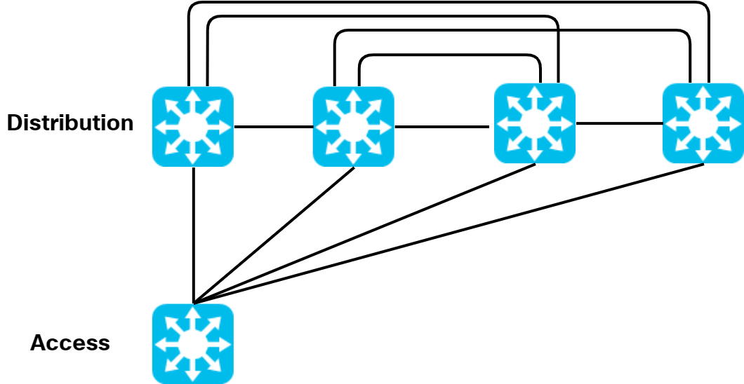
Moving from two to four distribution switches would cause this massively complex physical topology:
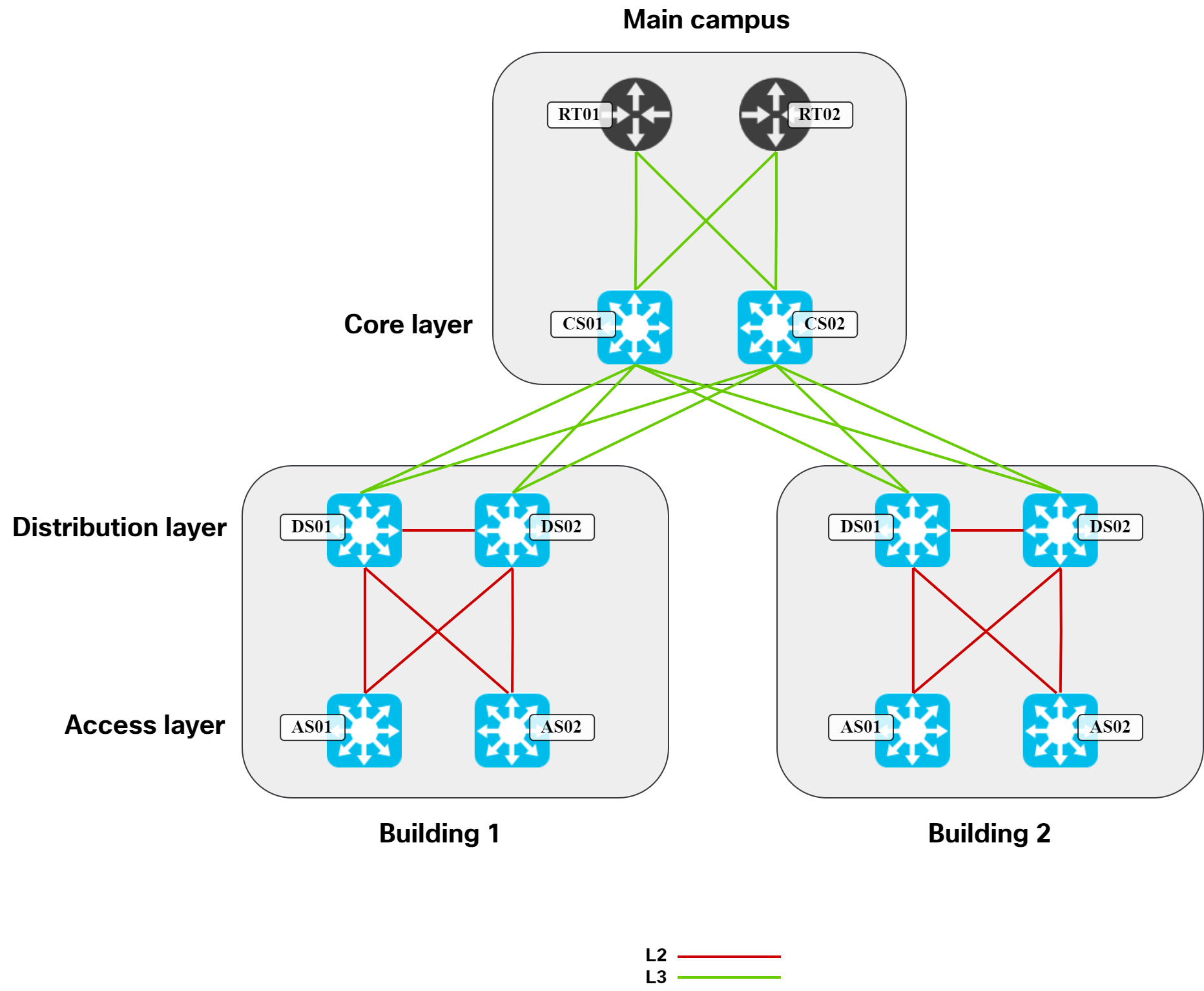
Going back to our traditional design, the diagram below shows what links are typically L2 vs L3:
Then let’s remove some of the links that STP would typically block:
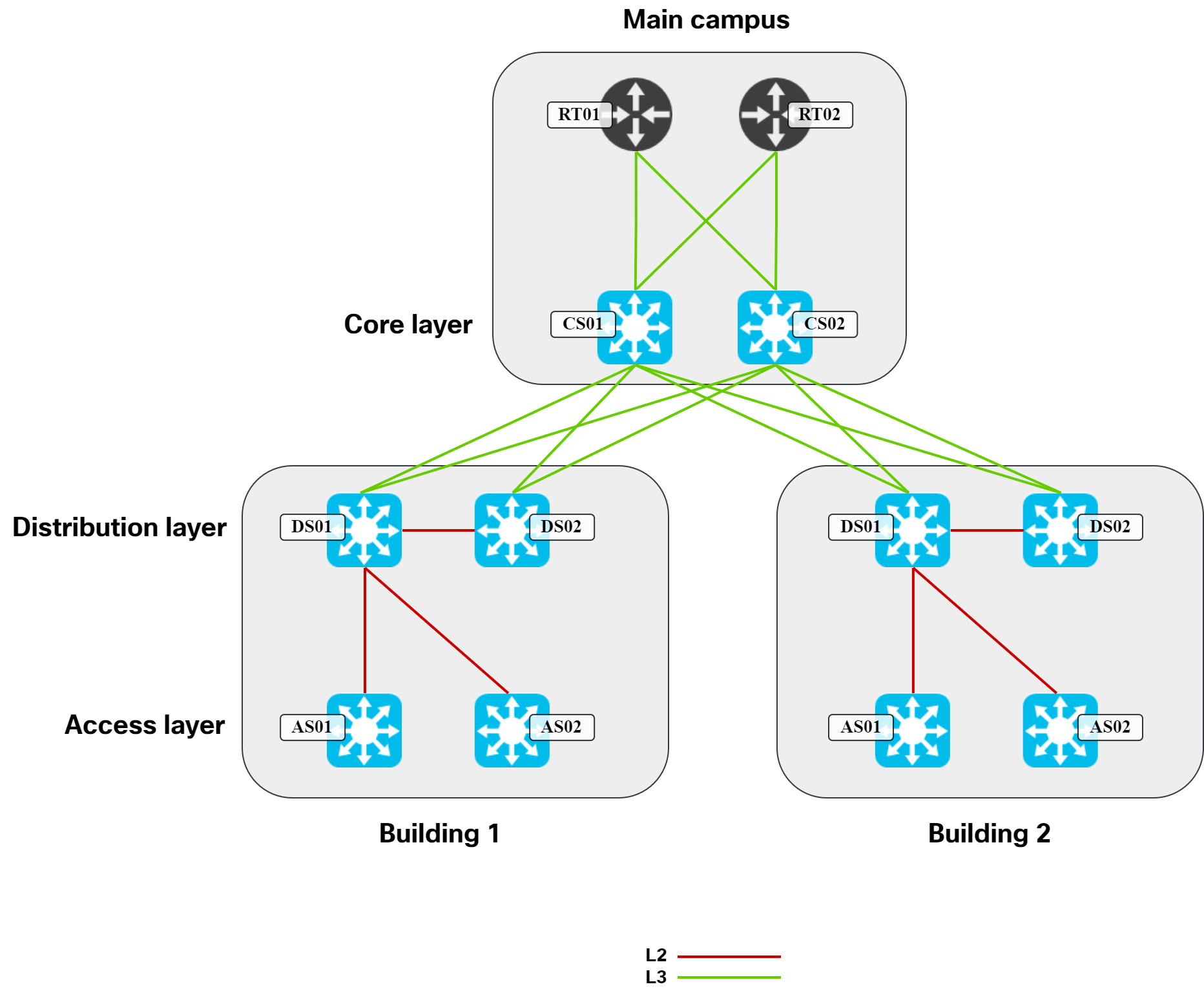
In this topology, it’s natural for DS01 to be the active gateway for hosts to align with the STP topology. It would certainly be possible to have DS02 be active, but it would be suboptimal as traffic would have to traverse the link between DS01 and DS02. When you see the topology drawn like this, it’s very evident that having multiple active gateways (anycast gateway), wouldn’t provide anything. Due to the looped L2 topology, STP must block links. With those links blocked, there is no viable path to use any other potential gateway. Not being able to use anycast gateway is therefore a consequence of the topology and protocols that we used in this type of design.
Now, just for the sake of it, let’s say we somehow could have looped L2 topology without any issues and all our links were forwarding. What problem would we run into then? Let’s look at a scenario below where a host is ARPing for its gateway:
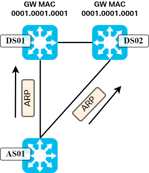
Both gateways would respond to the ARP request with ARP reply. What happens when those frames arrive at AS01? Remember, a switch populates its L2 forwarding table based on source MAC of frames received on ports. Here, the same MAC would be learned on two different ports. This is typically the sign of a bridging loop and would cause MAC flapping as the L2 forwarding table is updated each time it receives a frame with that MAC. It’s simply not possible to have anycast in this topology.
There is an exception to what I just described. How does Nexus achieve it using vPC? The key to that is:
- The two Nexus switches appear to be one in LACP messages.
- It’s then possible to form a portchannel.
- Having a portchannel removes the L2 loop.
- Still, only one switch will respond to ARP.
- They are both active in the data plane as both switches are allowed to consume frames with MAC of the specific L3 interface.
- vPC has it’s own mechanism for detecting and preventing loops.
With features like vPC it’s possible to overcome some of the shortcomings of a looped L2 topology. It does have its own set of complexity, though.
We now understand why anycast was never going to work with a traditional design, so what changed when we started building VXLAN/EVPN topologies? What changed is that we started building L3 networks with L2 as a service on top of it. Yes, we also started building leaf and spine networks, but the most significant change is that the gateway for hosts is now at the first hop of the topology. A typical topology is shown below:
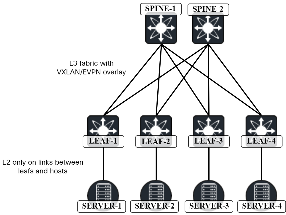
In this topology, ARP request from host towards gateway only travels on the link from host to leaf. There is no L2 between the leaf and the spine. There is no issue with the MAC being learned on multiple ports.
Having L3 at the access layer isn’t really new. We’ve seen this before in routed access networks. Could we have used anycast gateways in such a design as well? In theory, you could, but then you would have a lot of identical routes and with no L2 between them, this would be problematic. The reason why routed access didn’t see more popularity is that most networks have something that requires a L2 network. Be it the WiFi or some IoT-type connectivity.
To summarize, In the past where looped L2 topologies were the norm, MAC addresses needed to be unique in the L2 domain. Protocols like HSRP and VRRP used a virtual MAC, but only one node at a time would utilize the MAC address. When the leaf layer (access) started to use L3, there was no longer a need for unique MAC addresses as the L2 is local to the link between the host and the leaf. This is what enabled us to start using anycast gateways.
Great read as usual Daniel, keep it up!
Thanks!
thanks, nicee read.
Thanks!
Hi Daniel,
It’s super interesting to revisit things we take for granted. I’ve also seen your post on Linkedin and it’s fun to see how everybody approaches this question in the light of their expertise. Being more of an L2 guy, that’s how I see it:
Ethernet technology data plane is based on flooding traffic. That requires that there is a single path to a destination. If a mac address is reachable via more than one path, as you pointed out, it means that you have a loop in your network.
Mac learning is an optimization that limits the amount of flooding in your network (note that the mac address table, referred to as FDB in the IEEE standard is a “filtering database” not a “forwarding database” as everybody assumes.) Mac learning is based on the assumption that there is a single path to a destination: the mac address table s populated from snooping data plane traffic. That’s why it’s can’t handle two paths to the same destination -> seeing the same mac address on two ports is assumed to be a mac move, requiring an update to the mac address table. If the mac address table was a forwarding database, populated by a control plane (as it is in the routing model), then we could configure two paths for a given mac. Of course, it would require some accommodation in the data plane.
Anyway, all this implies that you cannot instantiate the same mac address in different locations in a traditional switched network. No need to invoke upper layer problems, if it does not work at L2, it does not work at L(2+N) 😉
The distributed LAG solutions (VPC, MC-LAG or whatever vendors call them) implement an anycast gateway while using traditional flood and learn model. How is that possible? This is because Layer 2 is actually comprised of multiple layers itself. The LAG is virtual link bundling multiple L2 links (VLANs are yet an additional layer 2 running above LAGs.) Mac learning run at the layer of the LAG and sees the bundle as a single link, so the anycast mac available on multiple links is not considered a mac move.
Anyway, I could be bloviating for ever on this, sorry for the long useless comment. I’ve just discovered your blog and I’
Francois! What a coincidence to see you here! I have just recently been going through a lot of posts from you on the Cisco community in regards to different interesting details of STP, encapsulations, etc.
This is a great way of describing it. The filtering database vs forwarding database is an interesting distinction. I didn’t think of it like that before. This is one of the nice things of posting that you get new perspectives.
Thank you!
Daniel, this is a great article, as usual!
I wanted to point out that your second figure, just below “Moving from two to four…complex physical topology”, has one more inter-Distribution link than needed to be the simplest fully-meshed topology for four switches. It only needs to be six links but, between the center two switches, you have two direct links: one straight and another above with rounded corners. It doesn’t change the narrative of why no AnycastGWs in the days of old, but I digress.
From the graph page at Wikipedia, https://en.wikipedia.org/wiki/Graph_(discrete_mathematics)
“In a graph of order n, the maximum degree of each vertex is n − 1, and the maximum number of edges is n(n − 1)/2.” Note: I snipped the reference to loops, but consider (n) as nodes, (n-1) as peers per node, and [n(n-1)/2] as total relationships to achieve full mesh.
listNodePeerLink = [(4,3,6), (5,4,10), (6,5,15), (8,7,28), (10,9,45), (12,11,66), (14,13,91), (16,15,120)]
As I’m sure you are aware and have probably written about, the same formula works for direct peering adjacencies, point-to-point tunnels, and anything where–when the number of nodes scales–so do the number of direct relationships between them all.
That is, until we have some technology to obfuscate the complexity behind a manageable number of devices having total visibility, such as two BGP route-reflectors, two DMVPN/NHRP hub routers, and so forth. Of course, for scaling up the usage of logical relationships like BGP and NHRP, we aren’t as constrained by physical resources having real costs, at least not initially. As example, I know there had been at least one 11,000-node DMVPN out there, although for sure using some regional hierarchies to collapse the control-plane burden so as to avoid having only two NHRP hub devices tracking (or not) 10,998 spoke nodes. Could you imagine, without DMVPN, just the configuration to have each router with 10,999 p2p tunnels? Yikes!
That said, even considering a “reasonable” 100-node overlay of p2p tunnels, we wouldn’t want to manage 99 tunnels per device, never mind that the routing protocol running over those would likely not keep up. Luckily, NHRP gave us the simplicity of having one or two hub devices tracking the other 99 or 98 spokes. There is often a threshold at which continuing to scale a layer further along the lateral plane begins to make less sense and we have to take some of the scale up hierarchically. It happened with Distribution switches needing to spread out, thus requiring Cores; with BGP peers leading to RRs; with p2p tunnels leading to NHRP/DMVPN; and, before long, Campus/DC Fabrics’ Spine layers may need to interconnect through one/more hierarchical Spine layer(s) above. I’ve seen customers maintain p2p iBGP peering with 18~20 switches in a DC, where I’d have preferred to go with a pair of RRs. At about 9-10 direct logical relationships in any protocol or tech, I’m looking for the consolidating feature like RR, NHRP, vManage/vSmart, etc. With physical connections, the ratio of usable-to-infrastructure ports needs to set the upper limit of scale before an additional layer is needed.
Thanks, as always, and best regards!
Great comment! Thanks, Rob!
Perfocto
many Thanks
Thank you!